background image

MISSION 1K●2K●3K 

SINGLE PHASE


Rev. 02 

– 19 March 2015


26 

6.5.4 Emergency Power Off (EPO) 

The EPO function  is used  to  shutdown the Ups by remote. This function, for example, can be used to turn off 
the load connected to the UPS by means of a thermal relay in case of over temperature in a room. 
When  the  EPO  is  activated, the  UPS  immediately  switches  off  the  output by  disconnecting  power  from  all  the 
loads connected, the Ups remain alarmed by  displaying the "EPO ON" message on  the  display, the Red  LED 
will turn on and start a continuous acoustic signaling. 
You can also activate the EPO function via the buttons on the Ups front panel. To do this, simultaneously press 
all three buttons for about a second. The ups will be in the same condition described above. 
In both conditions  to disable the  EPO function,  you must press the same combination of three keys, the  word 
"EPO OFF" will be displayed, the red LED will blink 2 times (at the same time with 2 beeps) every 4 seconds. 

To come back to normal operation press buttons 

+

  for selecting OFF. 

Now it is possible to restart the Ups by pressing buttons 

+

  ON. 


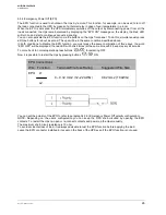
EPO Connections 

Wire    Function          Terminal Wire Size Rating            Suggested Wire Size 

EPO      L1 

                                  4 

– 0.32 mm2 (12–22 AWG)            0.82 mm2 (18 AWG) 

  L2 


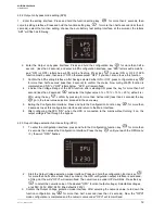
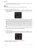
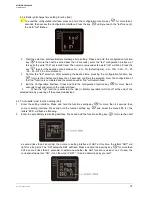
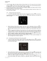
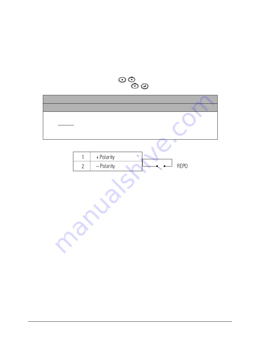
You can set the polarity of the EPO to refer to paragraph 4.3.8 (Emergency Power Off polarity configuration). 
NOTE:  Depending  on  the  user's  configuration  you  can  keep  the  UPS  short-circuited  by  opening  the  EPO 
contacts. To restart the Ups, re-open or re-connect contacts and power up the Ups manually. 
The maximum short-circuit resistance is 10 ohm. 
To avoid accidental loss of load, it is always advisable to test the EPO function before applying the load. 
Leave the EPO connector installed in its seat on the back of the UPS even if the EPO function is not used. 
 

Summary of Contents for MISSION 1000

Page 1: ...Uninterruptible Power Systems Mission 1K 2K 3K Single Phase UPS INSTRUCTION MANUAL...

Page 2: ...roubleshooting 22 6 3 EMC standard Safety standard 23 6 4 Product Performance 23 6 5 Communication interface 25 Manual instruction Thanks for purchasing our UPS it is safe and reliable so few maintena...

Page 3: ...of the UPS will cause electric shock or fire So don t place the containers equipped with liquid on the top of the UPS so as not to cause danger of electric shock and so on 4 Don t put the UPS in a pl...

Page 4: ...1K 2K 3K SINGLE PHASE Rev 02 19 March 2015 4 2 PRODUCT INTRODUCTION 2 1 The appearance of the product Fig 1 Front Panel view Fig 2 1KVA Rear Panel view Fig 3 2KVA Rear Panel view Fig 4 3KVA Rear Pane...

Page 5: ...Charger Standard unit provides 1A long backup unit provides 7A 7 Battery Sealed Lead Acid Battery 8 Output filter Complete filtering the output of the UPS to provide the clean power for loads 2 3 Mode...

Page 6: ...PS in a clean stable environment avoid the vibration dust too humidity flammable gas and liquid corrosive 2 The ambient temperature around UPS should keep in a range of 0 C 40 C If UPS works above 40...

Page 7: ...sing the external battery It is best to use external battery cable which matches with the equipment When connecting load to UPS first turn off load and then connect the power cable and finally turn on...

Page 8: ...re than 1 second in battery mode UPS runs the mute function INQUIRING key or Non function setting mode Press and hold the key for more than half a second less than 2 seconds Indicate the items of the...

Page 9: ...indication in different modes please refer to the LED display panel and warning table 4 1 3 LCD display functions The LCD displays as following picture LCD display comprises numerical value section ca...

Page 10: ...battery at the moment LCD shows that the output voltage is 0 which means UPS has no output If it is expected to have output of bypass you can set the bps ON by LCD setting menu 2 Press and hold the O...

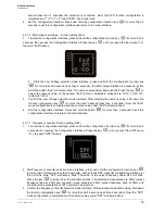
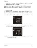
Page 11: ...ng off the UPS The operation of setting is as following 4 3 1 ECO mode setting 1 Enter the setting interface Press and hold the function setting key for more than 2 seconds then come to setting interf...

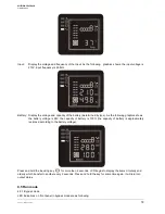
Page 12: ...5 default is 25 using the key confirm by pressing for more than half second less than 2 seconds the key go to the lower value selection proceed in the same way 5 Exiting the Configuration Interface Pr...

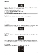
Page 13: ...on interface After selecting ON or OFF pressing the configuration function key for more than half second less than 2 seconds confirms the selection If OFF is selected the procedure ends and returns to...

Page 14: ...d function is completed and the selection under tod will remain fixed 4 Exit the Configuration Interface Press and hold the configuration function key for more than 2 seconds to exit and return to the...

Page 15: ...ct ON or OFF 3 Confirm the wc selection interface after selecting ON or OFF pressing and holding the configuration function key for more than half a second less than 2 seconds confirms the selection N...

Page 16: ...n half a second less than 2 seconds Now the Eod mode configuration is completed and the numeric value under Eod will remain fixed 4 Exit the configuration interface Press and hold the button for more...

Page 17: ...nquiring key or for more than half a second less than 2 seconds to inquire about items The inquired items include input battery output load temperature The displayed items on LCD screen are showed as...

Page 18: ...g graphics shows the battery voltage is 28V the capacity of battery is 100 the capacity of battery is approximately reckoned according to the battery voltage Press and hold the inquiring key for more...

Page 19: ...ne mode 4 5 3 Battery mode LED indications on front panel in battery mode are as following both the inverter green LED and battery yellow LED are on the buzzer beeps once every 4 seconds The warning r...

Page 20: ...l be fully discharge to low voltage protection shutdown Then it needs to be fully charged once 2 In high temperature area batteries should be manually charged and discharged once every two months The...

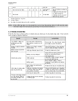
Page 21: ...in AC Normal voltage in bypass mode Once every two minutes Eliminate after starting the UPS Main AC high voltage warning in bypass mode Once every four seconds Main AC low voltage warning in bypass mo...

Page 22: ...input power cable and make a correct connection Battery capacity indicator flashes Battery low voltage or battery disconnected Check UPS battery connect battery well if battery damaged replace it Main...

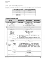
Page 23: ...range 186VAC 252VAC Current harmonic 7 100 non linear load OUTPUT Output style Single phase and earthing Rated voltage 208 220 230 240VAC Power factor 0 8 Voltage precision 2 Output Frequency Line mod...

Page 24: ...ttery Charge current A 1 Work Environment MODEL MISSION 1000 MISSION 2000 MISSION 3000 Temperature 0 C 40 C Relative humidity 0 95 non condensing Altitude 1500mt if 1500mt lower the rated power for us...

Page 25: ...is preferred 2 Intelligent slot The following intelligent cards can be installed into the intelligent slot of the UPS intelligent USB card intelligent SNMP card and intelligent dry contact card Suppor...

Page 26: ...EPO function you must press the same combination of three keys the word EPO OFF will be displayed the red LED will blink 2 times at the same time with 2 beeps every 4 seconds To come back to normal o...

Reviews: