en
Angle sensors
Date: 09.06.2020
9010020A00M - V01
19/20
f
Ensure the connections are not strained.
f
Connect the angle sensor in accordance with
the wire colours/connector pin assignments in
the data sheet.
f
Route the cable so that no damage can arise
(e.g. due to kinks, breaks, rubbing points).
Pleas take strain relief under consideration.
f
Route wires so that they are rigidly fixed if they
will be exposed to temperatures less than -5°C.
f
After installing, hand over the installation man-
ual to the end-user.
6.3 Putting into service
f
Ensure that the electrical specifications are ad-
hered to. The values must never be exceeded!
f
Do not apply or remove electrical connection
when under voltage.
f
Install entire system or the vehicle in an
EMC-compliant manner. The installation
environment influences the EMC of the angle
sensor. Install the angular sensor and route the
supply lines in a spatially separated manner or
at a great distance to lines with a high interfer-
ence levels (frequency converters, contactors,
etc.).
f
Connect the power and check operation of the
angle sensor.
f
Non-assigned outputs must no be connected.
9
The angle sensor is ready for operation.
Function check
NOTICE
Danger due to processes starting
inadvertently
f
During the function check during
use, be aware of other processes
starting inadvertently!
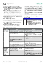
6.4 Faults/troubleshooting
Problem
Cause
Remedy
No or incor-
rect Signal
Angle sensor not correctly connected
due to plug connection assignment
f
Adhere to the data sheet for plug connec-
tion assignment.
External magnetic field
f
Angle sensor shielding
f
Remove/supress the external magnetic
field
Hall sensor defective
Demagnetisation of permanent
magnets
f
Replace the sensor / return it to the
factory
Connected cable defective due to
incorrect attachment
f
Cable replacement
f
Route the cable correctly
Zero-point position of the drive shaft
does not correspond to the actual
zero-point position.
f
Take the zero-point position of the drive
shaft under consideration
Damage of
housing
External mechanical or chemical
impact on the sensor
f
Replace the sensor.
Bearing
clearance
/ blockage
of the drive
shaft
Mechanical overload
f
Replace the sensor.
f
Contact elobau.
f
Please adhere to permissible mechanical
stress of the drive shaft.


