


14/20
9010020A00M - V01 Date:
09.06.2020
Angle sensors
en
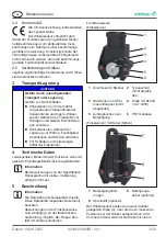
magnetic flux density changed by means of this
is detected by a hall sensor (3) and guided to the
plug connection (1) as an electrical signal.
The angle sensor doe not have any mechanical
stop. A mechanical stop is optionally possible
depending on the variant. The actual measuring
range can be found in the data sheet or the figure
type code.
Information
For actual applications contact elobau.
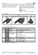
5.1 Type code
Type
424A
424R
424D
424C
424SD
424Z
5.1.1 Angle sensor 424A
Angle sensor, 30‒120 °, analogue signal, 1 output
Pos.
Example
Meaning
1‒4
424A
Reference
●
424A = angle sensor base number
5
0
Bearing
●
0 = plain bearing
●
1 = ball bearing
6
1
Output signal*
●
0 = 1-5 V
●
1 = 4‒20 mA
● 6 = 0.5‒4.5 V, radiometric
● 7 = 0.5‒4.5 V
7
A
Shaft
●
A = standard shaft
8‒10
030
Angle measuring
range
●
3 digits (value = angle)
e.g. 030 = 30 degrees
11
B
Actuation lever
●
B = Lever installed
For further details see the supplied datasheet.


