


16/20
9010020A00M - V01 Date:
09.06.2020
Angle sensors
en
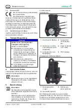
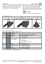
5.1.4 Angle sensor 424Z
Angle sensor, 30‒120°, analogue signal, redundant
Pos.
Example
Meaning
1‒4
424Z
Reference
●
424Z = angle sensor base number
5
P
Output
●
E = output 1
●
P = parallel
●
G = opposing
6‒8
030
Angle measuring
range
●
3 digits (value = angle)
e.g. 030 = 30 degrees
For further details see the supplied datasheet.
5.1.5 Angle sensor 424D
Angle sensor, 20‒360°, analogue signal, redundant
Pos.
Example
Meaning
1‒4
424D
Reference
●
424D = angle sensor base number
5
3
Output
●
1 = one output (CCW)*
●
2 = two outputs (CCW)*
●
3 = one output (CW)*
●
4 = two outputs (CW)*
●
5 = two outputs (opposing signal)
6
7
Output signal
● 0 = 1‒5 V
● 1 = 4‒50 mA
●
7 = 0.5‒4.5 V
●
P = PWM (on request)
7‒9
030
Angle measuring
range
●
3 digits (value = angle)
e.g. 030 = 30 degrees
10
B
Actuation lever
●
B = Lever installed
*CW = clockwise
*CCW = counterclockwise
For further details see the supplied datasheet.


