


18/20
9010020A00M - V01 Date:
09.06.2020
Angle sensors
en
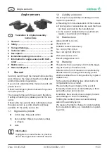
5.2 Optional accessories
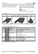
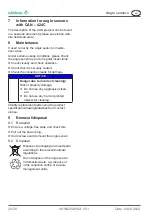
5.2.1 Actuation lever 350 210
10
50
R9
R7
Ø6
(2x)
The actuation lever is separately available or is
already pre-installed on the sensor depending on
the variant actually purchased.
●
Max. tightening torque of the fixing holes:
Adhere to 2.5 Nm
●
Use dowel pin type EN ISO 8752 Ø2x14 A2.
5.2.2 Wiring kit
Suitable wiring kits for the respective angle sen-
sor variants can be found in detail on the elobau
website.
Information
Optional accessories can be purchased
from elobau.
6
Installation/putting into service
NOTICE
Danger due to incorrect installation
Angles sensor can be damaged by
mechanical loads that are too high.
f
Avoid hitting the housing and the
drive shaft.
f
Comply with the electrical specifications.
f
Carefully remove the angle sensor from the
packaging.
f
Check all parts for damage.
Function check possible: Prior to installation, the
angle sensor can be connected and manually
operated and tested by rotating the drive shaft.
6.1 Mechanical connection
NOTICE
Danger due to incorrect installation
Angle sensor can be damaged.
f
Only use the designated holes /
bearing bushing for installation.
f
Use suitable fixing material.
f
Adhere to the tightening torques
(datasheet).
f
Observe the environmental conditions in se-
lecting the installation materials (seals, screws,
nuts, wall thickness, etc.).
f
Adhere to the zero-point position of the drive
shaft during installation. Please find information
concerning the zero-point position in the data
sheet.
6.2 Electrical connection
WARNING
Danger due to errors during elec-
trical connection of angle sensor.
Electronic components can be
destroyed, thereby resulting in mal-
functioning of the system, and hence,
injuries to personnel or property
damage.
f
Permissible specifications
concerning power, current and
voltage.
f
Values must not be exceeded.
Information
f
Please find electrical data in the
related data sheet.
f
Please find the connection assign-
ment of the plug connection as well
as a circuit diagram in the related
data sheet.
f
Signal path of the output is generally
depicted on the data sheet or is made
available by elobau on request.
f
Please pay attention to temperature
drift.


