Installation and use MR16
17
4.1.3 Connections to wired alarm control panel
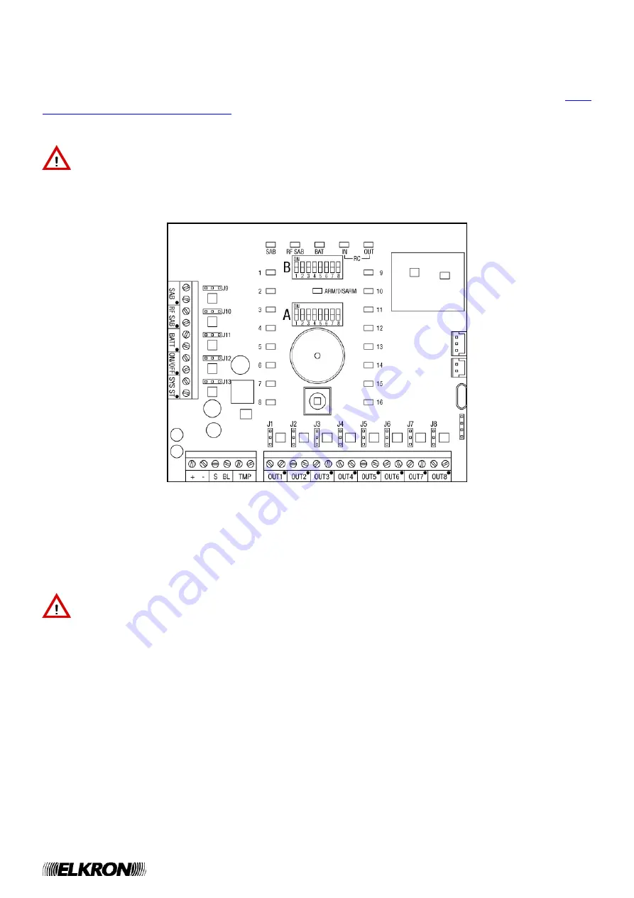
Relay output connection
Connect radio module relay
outputs
(figure 7) to wired alarm control panel inputs according to what
indicated in the table. Do not exceed voltages and currents accepted for solid state relays. The status of
the relay at rest (normally open or normally closed) is defined by DIP switches (see paragraph
4.1.4
Configuration of radio module MR16
configuration
). The LED between the two DIP switch banks indicates
radio module MR16 armed/disarmed status.
Warning:
the black dot identifies the pin, which, where the output is polarised to either 12 V or
0 V, switches over, following the input and its programming. The pin without a black dot has either
12 V or 0 V fixed potential independently of the status of associated radio device.
Where the radio output is not polarised, the two pins are similar to the ones of a circuit breaker.
Figure 7
Every wired alarm control panel follows specific conventions in naming its inputs and in the type of
connection (normal, balanced or with double balancing) to be made. In the table, for wired control panel
inputs, generic denominations are used. Refer to wired control panel instructions to identify correct inputs
and type of connection to be made.
Warning:
where radio module is connected to a wired control panel, you are warned against
programming, on wired control panel, functions (e.g. “Insertion Block”) preventing the system from
being armed when inputs are open.


