


M1XSP Installation Manual
Page 6
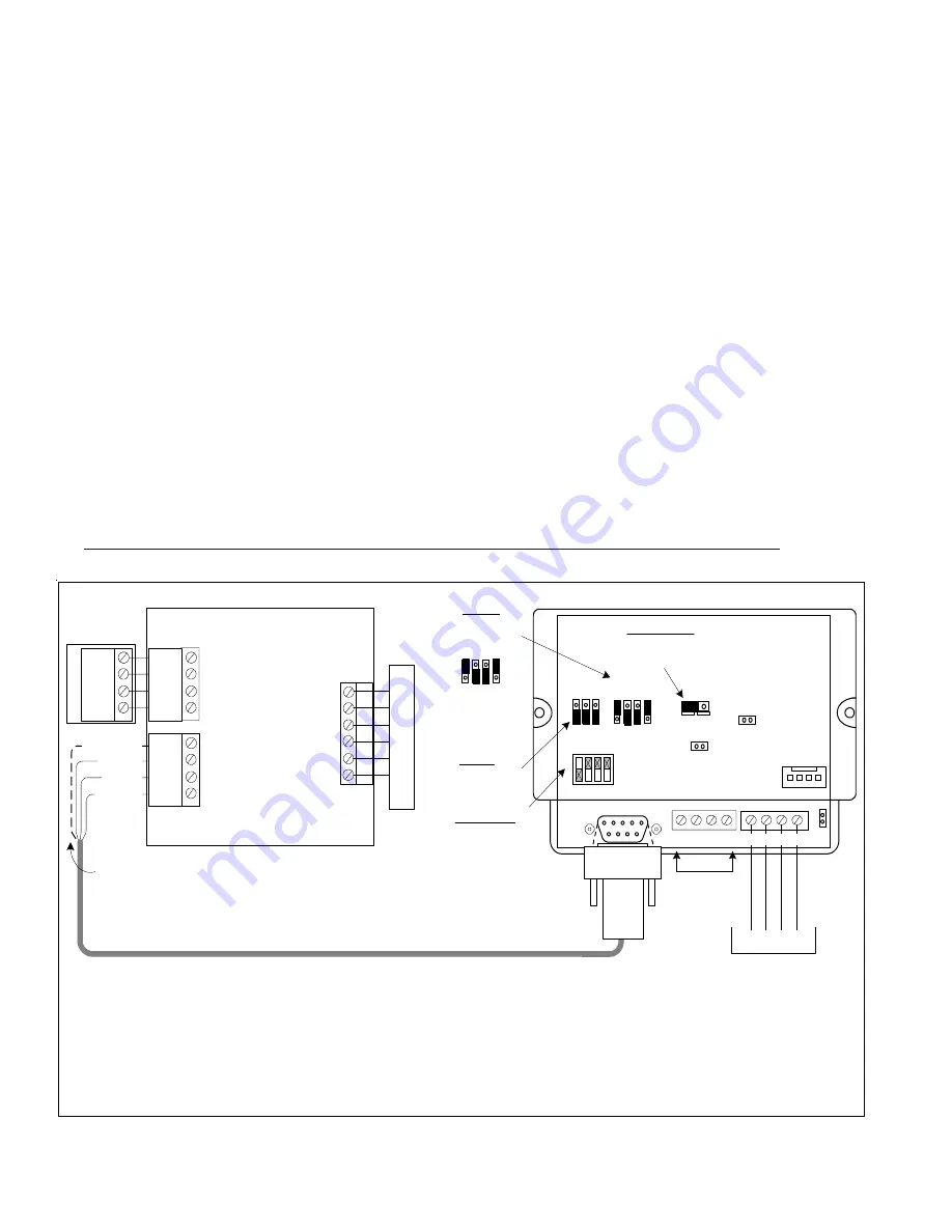
RS-485
Not Used
To M1 Control
Data Bus Terminals
Thermostat brand, interface format, and model of ELK-M1 Control dictates the total number of thermostats allowed.
The M1G supports 7 RCS-TR16 (RS-232 models). However, each thermostat requires a dedicated M1XSP.
NOTE: The ELK-M1G can support up to 16 of the RCS-TR16/TR40 (RS-485 models) using a single (1) M1XSP.
*
The ELK-M1 (Std) can only support 2 RCS thermostats.
+VKP A B Neg
ADDRESS
Switch 1 shown in ON
position (Address 1).
Switches 2,4,8 are Off.
MODE
For RCS
set to 1001 **
BAUD
No changes
needed.
Place plug on top
pins for a 1, on
bottom for a 0.
Address
1 2 4 8
ELK-M1XSP
Interface
1
0
1 2 3 4
RS-232
ON
232 485
JP1
JP2
JP3
+12V A B Neg JP5
Jumper JP3
must be in 232
position.
Part # WO37A - 10 ft. Cable with 4 flying leads
and DB9 connector
BAUD MODE
1
0
S1 S2 S3
S5 S6 S7 S8
** Early production units do not have the S5 Jumper
S5 S6 S7 S8
RCS TR16
"RS-232"
Control Unit
RS-232
GND
+12VDC
CLOCK
DATA
HVAC
SYST
EM
12V
GND
D +
D -
WDU
TS16
Wall Display
Unit
GND
+12VDC
CLOCK
DATA
GREEN
RED
BLACK
WHT (YEL)
Connection of White (Yel) wire is optional. It can
be used to 12VDC from the M1XSP to the
thermostat control unit in lieu of the HVAC power.
If not used, tape or insulate the White (Yel) wire.
1.
Install, and wire the RCS Control Unit and Wall Display Unit to the HVAC system per the RCS instructions.
2.
Install the ELK-M1XSP per the instructions on page 3. Be sure to enroll the device into the M1.
3.
Set the MODE jumpers S5=
1
, S6=
0
, S7=
0
, & S8=
1
for RCS mode. If the M1XSP has jumper S4, set it to =
1
. Set Jumper
JP3 to the "
232
" position. The BAUD jumpers S1,S2, & S3 do not matter as the RCS baud rate is preset internally.
4.
Connect the Black, Red, and Green wires from the ELK-WO37A cable to the RS-232 terminals on the RCS Thermostat
Control unit. The White (Yellow) wire is optional. It may be used to 12VDC from the M1XSP to the Thermostat in
lieu of the HVAC power. Consult the RCS manual for details. Plug the other end of the ELK-WO37A cable into the 9 pin
serial connector on the M1XSP.
5.
Power up the RCS Thermostat Control Unit.
6.
Program the Unit Address and any other options in the RCS Unit per its instructions. The unit address must match the
Thermostat number in the M1 Control. The first Thermostat should be Address 1.
7.
Using the ELK-RP Software, program the M1 using the following steps. Test and verify operation using steps d and e.
7a. Click on the Automation Tab in the ELK-RP software. Click on Thermostat icon and program a name for Thermostat 1.
7b. Click on the Task icon and program at least two tasks. Name the 1st Task "Economy Mode" and the 2nd "Comfort Mode".
7c. Click on the Rules icon and create the following 4 rules.
Whenever [Area Name] Armed State Becomes Armed Away
Whenever [Task Name] (Task 1) Is Activated
Then Activate [Economy Mode] (Task 1)
Then Set [Thermostat 1] (TStat 1) Cooling Desired Temp to 85 degrees
Whenever [Area] Armed State Becomes Disarmed
Whenever [Task Name] (Task 2) Is Activated
Then Activate [Comfort Mode] (Task 2)
Then Set [Thermostat 1] (TStat 1) Cooling Desired Temp to 70 degrees
7d. Use the M1 Keypad to verify the M1XSP & Thermostat operation. Press the ELK key followed by the Right arrow key to
access Menu 1-View/Control Automation Fncts. Press 6 for the Thermostat Temperature sub-menu, followed by Right
arrow key. The Keypad should display the first Thermostat (T01) along with its name and current temperature reading.
7e. Go into the Tasks sub-menu and select Economy Mode (Task 1). Press the # key to activate. When this task is activated
the thermostat cooling setpoint should go to 85 degrees. Confirm this on the Thermostat display.
RCS TR16 (RS-232 Format) Thermostat
The RCS TR16 (RS-232 Format) is rare and is replaced by the TR16/TR40 (RS485 Format) models.
Part # ELK-W046A - DB9 Serial Cable for M1XSP


