Elk Products ELK-M1XSP Installation Manual Download Page 11

M1XSP  Installation Manual

Page 11

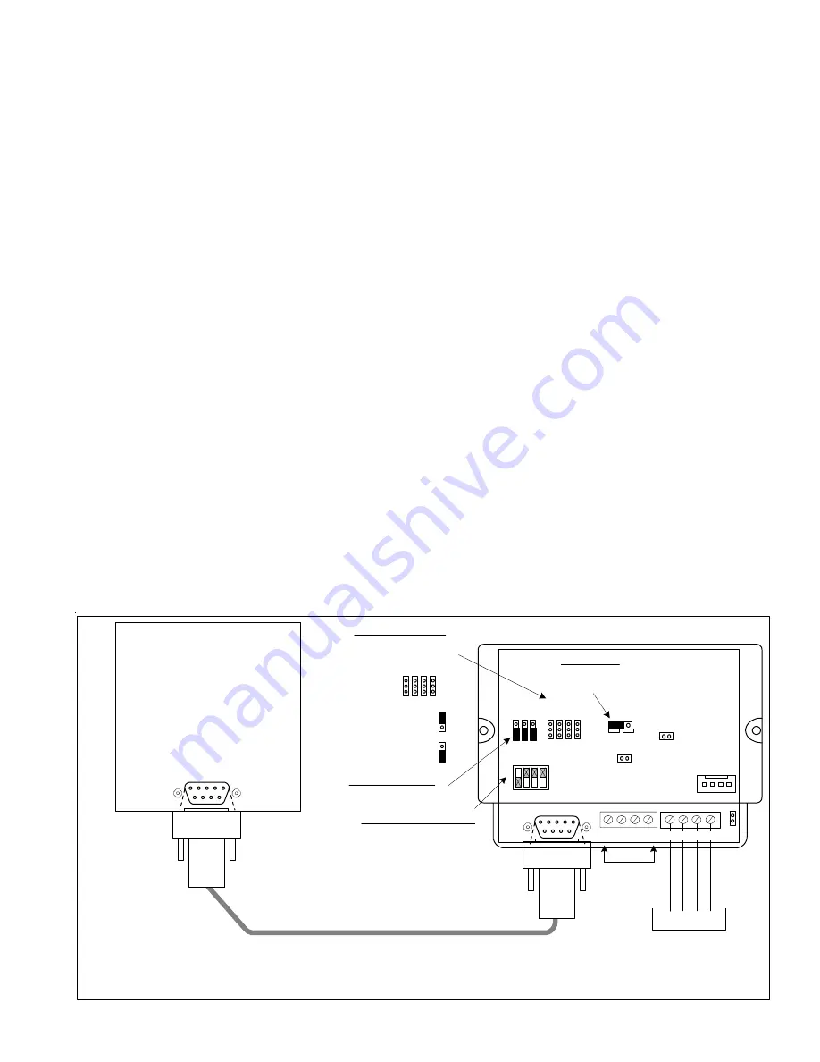
Lighting Controller Interface

or Circuit Board

RS-485

Not Used

To M1 Control

Data Bus Terminals

Consult the Lighting Manufacturer's Installation or Application Manual(s) for complete installation details.

+VKP A B Neg

ADDRESS SWITCHES

Switch 1 shown in ON

position (Address 1).

Switches 2,4,8 are Off.

 MODE  JUMPERS

Select according to the

table on Back Page.

1
0

 BAUD JUMPERS

No changes needed.

Address

1 2 4 8

ELK-M1XSP

Interface

1
0

1    2    3    4

RS-232

ON

232
485

JP1

JP2

JP3

+12V  A  B  Neg JP5

 Jumper JP3

must be in 232

position.

BAUD     MODE

Standard Computer type 9 Pin Serial Cable (Male/Female)

NOTE: Some manufacturers may supply a special cable.

RS-232

S1 S2 S3

S5 S6 S7 S8

S5 S6 S7 S8

1

0

Shorting plug on

top pins = 1,

bottom pins = 0.

** Older M1XSP units won't have the S5 and/or S4 Jumpers

Examples: OnQ-ALC, PCS-UPB, Centralite, Lutron, EDT-iLine, etc.

1.

Install Lighting Controller using the instructions provided by the manufacturer.  If the Lighting Controller's interface has an
address setting then set it to address 1.  Most controllers do not require an address setting.

3.

Install the ELK-M1XSP per the instructions on page 3.

4.

Set Jumper JP3 to the "232" position.

5.

Set the MODE jumpers to match the particular brand of lighting controller.  See chart on page 10.

6.

Set the BAUD rate jumpers to 

000

. (The M1XSP automatically sets the baud rate based on the MODE Jumper setting)

7.

Connect a 9-pin serial cable from the Lighting Controller's serial port to the 9 pin connector on the M1XSP.

8.

Apply power to the Lighting Controller and the M1XSP.  DON'T FORGET TO ENROLL THE M1XSP INTO THE M1.

9.

Program and test at least one light device using the ELK-RP Software and the following steps:

 9a. Click on the Automation icon, then on the Lighting icon.
 9b. Click on Lighting Device 1 and program the Name (1 to 16 characters), Format (manufacturer), and Type (switch,

dimmer, appliance).  The "Show" box may be left blank or checked ("X").  If this box is checked, the light will be included in
the scroll list of the Keypad and Telephone remote View/Control Automation menus.  If not selected for "Show" the light
will be available ONLY by manually entering the 3 digit number.  Click on the Voice Description to program a 1 to 6 word
voice description for this light.  Right click on Light 1 and select "Send Lighting 1" to send this programming to the M1.

 9c. Click on the Rules icon and create the following 2 test rules.

  Test Rule 1: WHENEVER 'Name' (Area 1) IS ARMED AWAY

THEN TURN 'Name' [1 [A1]] ON

  Test Rule 2: WHENEVER 'Name' (Area 1) IS DISARMED

THEN TURN 'Name' [1 [A1]] OFF

 9d. Click "Send" to transmit these rules to the M1.
 9e. Test the manual activation of this light by pressing the ELK key on the M1 Keypad followed by the Right arrow key to select

"Menu 1-View/Control Automation Fncts.  Press 2 for the Lighting submenu, followed by the Right arrow key.  The keypad
will display the first Light name and number along with its On or Off status.  Note: The status will not be correct if the M1 is
powered off.  To change the light from On to Off or from Off to On, press the # key.

 9f. Test the two automation rules by arming the control to the Away mode.  The light should come On.  Disarming the M1

should cause the light to turn Off.

10. This confirms the operation.  Continue to add or test additional lights as required.

Lighting Controllers with RS-232 "Serial" Interfaces

Summary of Contents for ELK-M1XSP

Page 1: ...the capabilities or data definitions to permit additional integration beyond what is currently available In addition Partner Mfgs may at their option add modify or discontinued features or support wit...

Page 2: ...ettings via DIP Switches Jumper Options and LED Diagnostic indicator On Board EOL Bus Termination Jumper Flash Memory for Firmware Updating SPECIFICATIONS Maximum of Expandable Ports Units 7 with M1G...

Page 3: ...HAI Thermostats numbered 1 thru 4 Data bus address 2 for HAI Thermostats numbered 5 to 8 Data bus address 3 for HAI Thermostats numbered 9 to 12 Data bus address 4 for HAI Thermostats numbered 13 to 1...

Page 4: ...AI OnQ ALC UPB Centralite EDT Dynalite LutronRA W800RF32 etc 10 x x Field Installable Firmware Uplink AnyNet and AES Intellinet Radio 20 x x Field Installable Firmware Vizia RZCOP ZWave interface Down...

Page 5: ...Aprilaire baud rate is preset internally 4 Plug the Aprilaire supplied 6 ft RJ to DB9 Cable between the 8811 Protocol Adapter and the ELK M1XSP DO NOT USE THE ELK WO37A CABLE 5 Power up the Aprilaire...

Page 6: ...unit The White Yellow wire is optional It may be used to supply 12VDC from the M1XSP to the Thermostat in lieu of the HVAC power Consult the RCS manual for details Plug the other end of the ELK WO37A...

Page 7: ...preset internally 4 Using a 3 conductor cable and the diagram below connect the GND D and D wires from the RS 485 terminals on the RCS Thermostat Control unit to the RS 485 terminals on the M1XSP The...

Page 8: ...OmniStat 2 series the M1XSP must be firmware updated to version 70 0 2 or the latest 70 x x version 4 Set the M1XSP MODE jumpers to S5 1 S6 0 S7 1 S8 0 If the M1XSP has jumper S4 set it to 1 5 Set th...

Page 9: ...Data Bus Terminals VKP A B Neg ADDRESS Only Addresses 1 2 3 or 4 can be used with HAI Stats Address 1 shown Switch 1 on MODE For HAI set to 1010 1 0 Address 1 2 4 8 ELK M1XSP Interface 1 0 1 2 3 4 RS...

Page 10: ...assigned to Carrier System 2 Zone 2 Elk Thermostat 3 is assigned to Carrier System 1 Zone 3 Elk Thermostat 11 is assigned to Carrier System 2 Zone 3 Elk Thermostat 4 is assigned to Carrier System 1 Z...

Page 11: ...T FORGET TO ENROLL THE M1XSP INTO THE M1 9 Program and test at least one light device using the ELK RP Software and the following steps 9a Click on the Automation icon then on the Lighting icon 9b Cli...

Page 12: ...only support ALC 4 button scene switches wired and connected on ALC branch 1 Setting up the M1XSP and the M1 to communicate with OnQ ALC 1 Install the ELK M1XSP per the instructions on page 3 Be sure...

Page 13: ...4 F15 F16 G01 G02 G03 G04 G05 G06 G07 G08 G09 G10 G11 G12 G13 G14 G15 G16 H01 H02 H03 H04 H05 H06 H07 H08 H09 H10 H11 H12 H13 H14 H15 H16 ELK Light Device 129 130 131 132 133 134 135 136 137 138 139 1...

Page 14: ...individual addresses program M1 Lighting devices 1 192 as Format Serial Expander Type Dimmer or On Off Switch if the device isn t dimmable For UPB link addresses program M1 Lighting devices 193 256 a...

Page 15: ...1 192 PLC X 10 Ref I01 I02 I03 I04 I05 I06 I07 I08 I09 I10 I11 I12 I13 I14 I15 I16 J01 J02 J03 J04 J05 J06 J07 J08 J09 J10 J11 J12 J13 J14 J15 J16 K01 K02 K03 K04 K05 K06 K07 K08 K09 K10 K11 K12 K13 K...

Page 16: ...pander Type On Off Switch Load Status and or Limitations with Elegance and LiteJet The wallplate button press feature with LiteJet Elegance is not directly usable with M1 However by assigning a button...

Page 17: ...172 173 174 175 176 177 178 179 180 181 182 183 184 185 186 187 188 189 190 191 192 PLC X 10 Ref I01 I02 I03 I04 I05 I06 I07 I08 I09 I10 I11 I12 I13 I14 I15 I16 J01 J02 J03 J04 J05 J06 J07 J08 J09 J10...

Page 18: ...nd 17 All On All Off respectively Program the name for light device 16 as All On Off Set the Format to Serial Expander and Type to On Off Switch Activating M1 lighting 16 On it will send Phantom 16 Ac...

Page 19: ...2 163 164 165 166 167 168 169 170 171 172 173 174 175 176 177 178 179 180 181 182 183 184 185 186 187 188 189 190 191 192 PLC X 10 Ref I01 I02 I03 I04 I05 I06 I07 I08 I09 I10 I11 I12 I13 I14 I15 I16 J...

Page 20: ...nked learned into the M1XSP starting at the first M1 Lighting device 001 A1 Using just the M1XSP there is no way to have devices start at a specific location INSTEON devices cannot be removed or re ar...

Page 21: ...e Right arrow key to access Menu 1 View Control Automation Fncts Press 2 followed by the right arrow key for the Lighting sub menu Advance to M1 Light 256 INSTEON LinkMode by entering 2 5 6 2 Turn ON...

Page 22: ...s an option to eliminate Groups and free up addresses 193 M1 to 254 P14 See note N2 below N1 With the M1XSP Jumper S5 0 factory setting the M1XSP supports a total of 192 individual INSTEON or X 10 Lig...

Page 23: ...H14 H15 H16 ELK Light Device 129 130 131 132 133 134 135 136 137 138 139 140 141 142 143 144 145 146 147 148 149 150 151 152 153 154 155 156 157 158 159 160 161 162 163 164 165 166 167 168 169 170 17...

Page 24: ...s c RS 232 Setup this may show up as HAI SETUP in some older remotes For helpful information about the ViziaRF configuration use the following link to the Leviton web site http www leviton com OA_HTML...

Page 25: ...be set as Backup B Optional Program a name to describe the location that this telephone number is reporting to C Do not program any numbers into the NUMBER TO DIAL location D Program the reporting for...

Page 26: ...ignals onto the AC powerline if equipped with a PSC05 PLC interface Please note that M1 rules can only be activated by ON or OFF commands from these devices There is no rule activation support for DIM...

Page 27: ...the AES Radio to be positioned far from the control 6 Construct a Serial Connection Cable from the M1XSP to the AES Radio Unit using the diagram below This cable requires a DB9F 9 Pin Female connecto...

Page 28: ...ING ELKRP SOFTWARE MAKE SURE TO SEND ALL OF THIS PROGRAMMING TO THE CONTROL 10 Test Test Test It is very important to test each of the reported events SUPERVISION The M1XSP is enrolled with M1 Control...

Page 29: ...esignated A and A1 Do the same for the data B White wire At the control splice the A1 and B1 wires to the A and B wires going to the next device Terminate the last wired device and the control JP3 ONL...

Page 30: ...keys to exit Installer Programming 1234567890123456789012345 1234567890123456789012345 1234567890123456789012345 1234567890123456789012345 1234567890123456789012345 1234567890123456789012345 12345678...

Page 31: ...M1XSP InstallationManual Page 31 THIS PAGE INTENTIONALLY LEFT BLANK...

Page 32: ...engage a 120 Ohm resistor for terminating the M1 RS 485 Data Bus See M1 Data bus wiring instructions before use JP2 Used to engage a 120 Ohm resistor for terminating the Outbound External RS 485 Data...

Reviews: