Elk Products ELK-M1XSP Installation Manual Download Page 19

M1XSP  Installation Manual

Page 19

Lutron

Phantom

 Buttons

Phantom 1
Phantom 2
Phantom 3
Phantom 4
Phantom 5
Phantom 6
Phantom 7
Phantom 8
Phantom 9

Phantom 10
Phantom 11
Phantom 12
Phantom 13
Phantom 14
Phantom 15

B16/17 All On/Off

Phantom 1
Phantom 2
Phantom 3
Phantom 4
Phantom 5
Phantom 6
Phantom 7
Phantom 8
Phantom 9

Phantom 10
Phantom 11
Phantom 12
Phantom 13
Phantom 14
Phantom 15

B16 All On/Off

Lighting Zn1 (S1)
Lighting Zn2 (S1)
Lighting Zn3 (S1)
Lighting Zn4 (S1)
Lighting Zn5 (S1)
Lighting Zn6 (S1)
Lighting Zn7 (S1)
Lighting Zn8 (S1)
Lighting Zn9 (S1)

Lighting Zn10 (S1)
Lighting Zn11 (S1)
Lighting Zn12 (S1)
Lighting Zn13 (S1)
Lighting Zn14 (S1)
Lighting Zn15 (S1)
Lighting Zn16 (S1)
Lighting Zn17 (S1)
Lighting Zn18 (S1)
Lighting Zn19 (S1)
Lighting Zn20 (S1)
Lighting Zn21 (S1)
Lighting Zn22 (S1)
Lighting Zn23 (S1)
Lighting Zn24 (S1)
Lighting Zn25 (S1)
Lighting Zn26 (S1)
Lighting Zn27 (S1)
Lighting Zn28 (S1)
Lighting Zn29 (S1)
Lighting Zn30 (S1)
Lighting Zn31 (S1)
Lighting Zn32 (S1)

ELK

Light

Device

1
2
3
4
5
6
7
8
9

10
11
12
13
14
15
16

17
18
19
20
21
22
23
24
25
26
27
28
29
30
31
32

33
34
35
36
37
38
39
40
41
42
43
44
45
46
47
48
49
50
51
52
53
54
55
56
57
58
59
60
61
62
63
64

PLC

(X-10)

Ref.

A01
A02
A03
A04
A05
A06
A07
A08
A09
A10
A11
A12
A13
A14
A15
A16

B01
B02
B03
B04
B05
B06
B07
B08
B09
B10
B11
B12
B13
B14
B15
B16

C01
C02
C03
C04
C05
C06
C07
C08
C09
C10
C11
C12
C13
C14
C15
C16
D01
D02
D03
D04
D05
D06
D07
D08
D09
D10
D11
D12
D13
D14
D15
D16

Expanded

Zones 2nd Sys

as Lights (S2)

Lighting Z1 (S2)
Lighting Z2 (S2)
Lighting Z3 (S2)
Lighting Z4 (S2)
Lighting Z5 (S2)
Lighting Z6 (S2)
Lighting Z7 (S2)
Lighting Z8 (S2)
Lighting Z9 (S2)

Lighting Z10 (S2)
Lighting Z11 (S2)
Lighting Z12 (S2)
Lighting Z13 (S2)
Lighting Z14 (S2)
Lighting Z15 (S2)
Lighting Z16 (S2)
Lighting Z17 (S2)
Lighting Z18 (S2)
Lighting Z19 (S2)
Lighting Z20 (S2)
Lighting Z21 (S2)
Lighting Z22 (S2)
Lighting Z23 (S2)
Lighting Z24 (S2)
Lighting Z25 (S2)
Lighting Z26 (S2)
Lighting Z27 (S2)
Lighting Z28 (S2)
Lighting Z29 (S2)
Lighting Z30 (S2)
Lighting Z31 (S2)
Lighting Z32 (S2)

Phantom 1
Phantom 2
Phantom 3
Phantom 4
Phantom 5
Phantom 6
Phantom 7
Phantom 8
Phantom 9

Phantom 10
Phantom 11
Phantom 12
Phantom 13
Phantom 14
Phantom 15

B16 All On/Off

Shade Z1 (S1)
Shade Z2 (S1)
Shade Z3 (S1)
Shade Z4 (S1)
Shade Z5 (S1)
Shade Z6 (S1)
Shade Z7 (S1)
Shade Z8 (S1)
Shade Z9 (S1)

Shade Z10 (S1)
Shade Z11 (S1)
Shade Z12 (S1)
Shade Z13 (S1)
Shade Z14 (S1)
Shade Z15 (S1)
Shade Z16 (S1)

ELK

Light

Device

65
66
67
68
69
70
71
72
73
74
75
76
77
78
79
80
81
82
83
84
85
86
87
88
89
90
91
92
93
94
95
96

97
98
99

100
101
102
103
104
105
106
107
108
109
110
111
112

113
114
115
116
117
118
119
120
121
122
123
124
125
126
127
128

PLC

(X-10)

Ref.

E01
E02
E03
E04
E05
E06
E07
E08
E09
E10
E11
E12
E13
E14
E15
E16
F01
F02
F03
F04
F05
F06
F07
F08
F09
F10
F11
F12
F13
F14
F15
F16

G01
G02
G03
G04
G05
G06
G07
G08
G09
G10
G11
G12
G13
G14
G15
G16

H01
H02
H03
H04
H05
H06
H07
H08
H09
H10
H11
H12
H13
H14
H15
H16

ELK

Light

Device

129
130
131
132
133
134
135
136
137
138
139
140
141
142
143
144

145
146
147
148
149
150
151
152
153
154
155
156
157
158
159
160
161
162
163
164
165
166
167
168
169
170
171
172
173
174
175
176

177
178
179
180
181
182
183
184
185
186
187
188
189
190
191
192

PLC

(X-10)

Ref.

I01
I02
I03
I04
I05
I06
I07
I08
I09
I10
I11
I12
I13
I14
I15
I16

J01
J02
J03
J04
J05
J06
J07
J08
J09
J10
J11
J12
J13
J14
J15
J16

K01
K02
K03
K04
K05
K06
K07
K08
K09
K10
K11
K12
K13
K14
K15
K16

L01
L02
L03
L04
L05
L06
L07
L08
L09
L10
L11
L12
L13
L14
L15
L16

ELK

Light

Device

193
194
195
196
197
198
199
200
201
202
203
204
205
206
207
208
209
210
211
212
213
214
215
216
217
218
219
220
221
222
223
224
225
226
227
228
229
230
231
232
233
234
235
236
237
238
239
240
241
242
243
244
245
246
247
248
249
250
251
252
253
254
255
256

Zones 1st Sys

as Shades (S1)

Shade Z17 (S1)
Shade Z18 (S1)
Shade Z19 (S1)
Shade Z20 (S1)
Shade Z21 (S1)
Shade Z22 (S1)
Shade Z23 (S1)
Shade Z24 (S1)
Shade Z25 (S1)
Shade Z26 (S1)
Shade Z27 (S1)
Shade Z28 (S1)
Shade Z29 (S1)
Shade Z30 (S1)
Shade Z31 (S1)
Shade Z32 (S1)

Shade Z1 (S2)
Shade Z2 (S2)
Shade Z3 (S2)
Shade Z4 (S2)
Shade Z5 (S2)
Shade Z6 (S2)
Shade Z7 (S2)
Shade Z8 (S2)
Shade Z9 (S2)

Shade Z10 (S2)
Shade Z11 (S2)
Shade Z12 (S2)
Shade Z13 (S2)
Shade Z14 (S2)
Shade Z15 (S2)
Shade Z16 (S2)
Shade Z17 (S2)
Shade Z18 (S2)
Shade Z19 (S2)
Shade Z20 (S2)
Shade Z21 (S2)
Shade Z22 (S2)
Shade Z23 (S2)
Shade Z24 (S2)
Shade Z25 (S2)
Shade Z26 (S2)
Shade Z27 (S2)
Shade Z28 (S2)
Shade Z29 (S2)
Shade Z30 (S2)
Shade Z31 (S2)
Shade Z32 (S2)

MC1 Btn  1
MC1 Btn  2
MC1 Btn  3
MC1 Btn  4
MC1 Btn  5

MC1 All On/Off

MC2 Btn  1
MC2 Btn  2
MC2 Btn  3
MC2 Btn  4
MC2 Btn  5

MC2 All On/Off

MC3 Btn  1
MC3 Btn  2
MC3 Btn  3
MC3 Btn  4

Lutron

Master Ctrl Buttons

MC3 Btn  5

MC3 All On/Off

MC4 Btn  1
MC4 Btn  2
MC4 Btn  3
MC4 Btn  4
MC4 Btn  5

MC4 All On/Off

MC5 Btn 


1

MC5 Btn  2
MC5 Btn  3
MC5 Btn  4
MC5 Btn  5

MC5 All On/Off

MC6 Btn  1
MC6 Btn  2
MC6 Btn  3
MC6 Btn  4
MC6 Btn  5

MC6 All On/Off

MC7 Btn  1
MC7 Btn  2
MC7 Btn  3
MC7 Btn  4
MC7 Btn  5

MC7 All On/Off

MC8 Btn  1
MC8 Btn  2
MC8 Btn  3
MC8 Btn  4
MC8 Btn  5

MC8 All On/Off

MC9 Btn  1
MC9 Btn  2
MC9 Btn  3
MC9 Btn  4
MC9 Btn  5

MC9 All On/Off

MC10 Btn  1
MC10 Btn  2
MC10 Btn  3
MC10 Btn  4
MC10 Btn  5

MC10 All On/Off

MC11 Btn  1
MC11 Btn  2
MC11 Btn  3
MC11 Btn  4
MC11 Btn  5

MC11 All On/Off

MC12 Btn  1
MC12 Btn  2
MC12 Btn  3
MC12 Btn  4
MC12 Btn  5

MC12 All On/Off

PLC

(X-10)

Ref.

M01
M02
M03
M04
M05
M06
M07
M08
M09
M10
M11
M12
M13
M14
M15
M16

N01
N02
N03
N04
N05
N06
N07
N08
N09
N10
N11
N12
N13
N14
N15
N16
O01
O02
O03
O04
O05
O06
O07
O08
O09
O10
O11
O12
O13
O14
O15

016
P01
P02
P03
P04
P05
P06
P07
P08
P09
P10
P11
P12
P13
P14
P15
P16

Zones 1st Sys

as Lights (S1)

Security

Flash Mode

Security

Solid Mode

Zones 1st Sys

as Shades (S1)

Zones 2nd Sys

as Shades (S2)

Master Control

Buttons

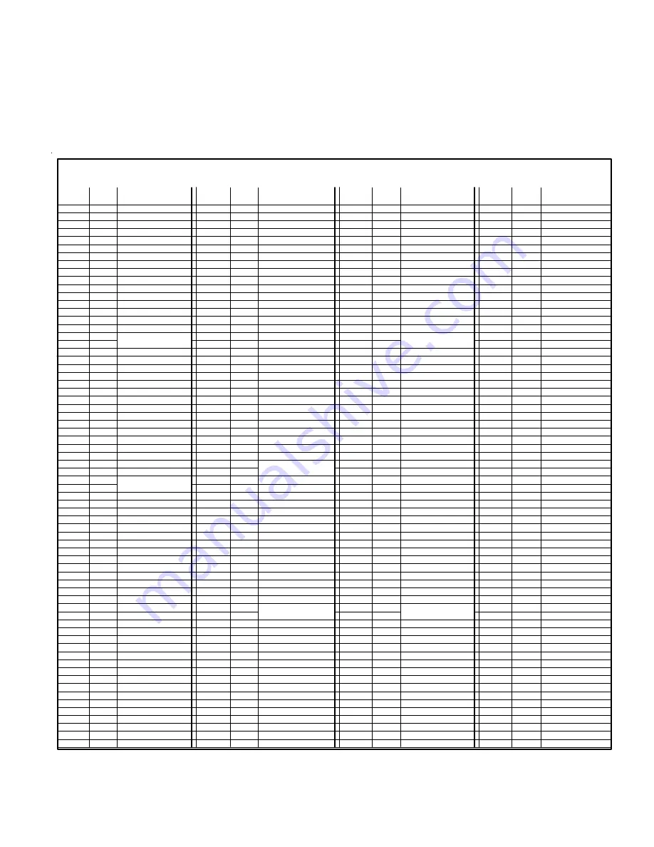
M1 Lighting Devices Mapped to Lutron Radio RA

M1 Light Devices 177 thru 248 

correspond to Lutron RA 

buttons on Master Control units 1 thru 12.  

Unused (unassigned)

buttons can be used, with restrictions, to initiate rule triggers in the M1.  Buttons that are already assigned to activate or
display phantoms or zones SHOULD NOT BE USED as rule triggers simply because the state of the button can be out-of-
sync with the M1, preventing a transition change from occurring.  NOTE: Master Control units buttons are Receive ONLY.
The M1 cannot directly activate or control any of the Master Control unit buttons.

Lutron 1st  Generation RA - (continued)

Summary of Contents for ELK-M1XSP

Page 1: ...the capabilities or data definitions to permit additional integration beyond what is currently available In addition Partner Mfgs may at their option add modify or discontinued features or support wit...

Page 2: ...ettings via DIP Switches Jumper Options and LED Diagnostic indicator On Board EOL Bus Termination Jumper Flash Memory for Firmware Updating SPECIFICATIONS Maximum of Expandable Ports Units 7 with M1G...

Page 3: ...HAI Thermostats numbered 1 thru 4 Data bus address 2 for HAI Thermostats numbered 5 to 8 Data bus address 3 for HAI Thermostats numbered 9 to 12 Data bus address 4 for HAI Thermostats numbered 13 to 1...

Page 4: ...AI OnQ ALC UPB Centralite EDT Dynalite LutronRA W800RF32 etc 10 x x Field Installable Firmware Uplink AnyNet and AES Intellinet Radio 20 x x Field Installable Firmware Vizia RZCOP ZWave interface Down...

Page 5: ...Aprilaire baud rate is preset internally 4 Plug the Aprilaire supplied 6 ft RJ to DB9 Cable between the 8811 Protocol Adapter and the ELK M1XSP DO NOT USE THE ELK WO37A CABLE 5 Power up the Aprilaire...

Page 6: ...unit The White Yellow wire is optional It may be used to supply 12VDC from the M1XSP to the Thermostat in lieu of the HVAC power Consult the RCS manual for details Plug the other end of the ELK WO37A...

Page 7: ...preset internally 4 Using a 3 conductor cable and the diagram below connect the GND D and D wires from the RS 485 terminals on the RCS Thermostat Control unit to the RS 485 terminals on the M1XSP The...

Page 8: ...OmniStat 2 series the M1XSP must be firmware updated to version 70 0 2 or the latest 70 x x version 4 Set the M1XSP MODE jumpers to S5 1 S6 0 S7 1 S8 0 If the M1XSP has jumper S4 set it to 1 5 Set th...

Page 9: ...Data Bus Terminals VKP A B Neg ADDRESS Only Addresses 1 2 3 or 4 can be used with HAI Stats Address 1 shown Switch 1 on MODE For HAI set to 1010 1 0 Address 1 2 4 8 ELK M1XSP Interface 1 0 1 2 3 4 RS...

Page 10: ...assigned to Carrier System 2 Zone 2 Elk Thermostat 3 is assigned to Carrier System 1 Zone 3 Elk Thermostat 11 is assigned to Carrier System 2 Zone 3 Elk Thermostat 4 is assigned to Carrier System 1 Z...

Page 11: ...T FORGET TO ENROLL THE M1XSP INTO THE M1 9 Program and test at least one light device using the ELK RP Software and the following steps 9a Click on the Automation icon then on the Lighting icon 9b Cli...

Page 12: ...only support ALC 4 button scene switches wired and connected on ALC branch 1 Setting up the M1XSP and the M1 to communicate with OnQ ALC 1 Install the ELK M1XSP per the instructions on page 3 Be sure...

Page 13: ...4 F15 F16 G01 G02 G03 G04 G05 G06 G07 G08 G09 G10 G11 G12 G13 G14 G15 G16 H01 H02 H03 H04 H05 H06 H07 H08 H09 H10 H11 H12 H13 H14 H15 H16 ELK Light Device 129 130 131 132 133 134 135 136 137 138 139 1...

Page 14: ...individual addresses program M1 Lighting devices 1 192 as Format Serial Expander Type Dimmer or On Off Switch if the device isn t dimmable For UPB link addresses program M1 Lighting devices 193 256 a...

Page 15: ...1 192 PLC X 10 Ref I01 I02 I03 I04 I05 I06 I07 I08 I09 I10 I11 I12 I13 I14 I15 I16 J01 J02 J03 J04 J05 J06 J07 J08 J09 J10 J11 J12 J13 J14 J15 J16 K01 K02 K03 K04 K05 K06 K07 K08 K09 K10 K11 K12 K13 K...

Page 16: ...pander Type On Off Switch Load Status and or Limitations with Elegance and LiteJet The wallplate button press feature with LiteJet Elegance is not directly usable with M1 However by assigning a button...

Page 17: ...172 173 174 175 176 177 178 179 180 181 182 183 184 185 186 187 188 189 190 191 192 PLC X 10 Ref I01 I02 I03 I04 I05 I06 I07 I08 I09 I10 I11 I12 I13 I14 I15 I16 J01 J02 J03 J04 J05 J06 J07 J08 J09 J10...

Page 18: ...nd 17 All On All Off respectively Program the name for light device 16 as All On Off Set the Format to Serial Expander and Type to On Off Switch Activating M1 lighting 16 On it will send Phantom 16 Ac...

Page 19: ...2 163 164 165 166 167 168 169 170 171 172 173 174 175 176 177 178 179 180 181 182 183 184 185 186 187 188 189 190 191 192 PLC X 10 Ref I01 I02 I03 I04 I05 I06 I07 I08 I09 I10 I11 I12 I13 I14 I15 I16 J...

Page 20: ...nked learned into the M1XSP starting at the first M1 Lighting device 001 A1 Using just the M1XSP there is no way to have devices start at a specific location INSTEON devices cannot be removed or re ar...

Page 21: ...e Right arrow key to access Menu 1 View Control Automation Fncts Press 2 followed by the right arrow key for the Lighting sub menu Advance to M1 Light 256 INSTEON LinkMode by entering 2 5 6 2 Turn ON...

Page 22: ...s an option to eliminate Groups and free up addresses 193 M1 to 254 P14 See note N2 below N1 With the M1XSP Jumper S5 0 factory setting the M1XSP supports a total of 192 individual INSTEON or X 10 Lig...

Page 23: ...H14 H15 H16 ELK Light Device 129 130 131 132 133 134 135 136 137 138 139 140 141 142 143 144 145 146 147 148 149 150 151 152 153 154 155 156 157 158 159 160 161 162 163 164 165 166 167 168 169 170 17...

Page 24: ...s c RS 232 Setup this may show up as HAI SETUP in some older remotes For helpful information about the ViziaRF configuration use the following link to the Leviton web site http www leviton com OA_HTML...

Page 25: ...be set as Backup B Optional Program a name to describe the location that this telephone number is reporting to C Do not program any numbers into the NUMBER TO DIAL location D Program the reporting for...

Page 26: ...ignals onto the AC powerline if equipped with a PSC05 PLC interface Please note that M1 rules can only be activated by ON or OFF commands from these devices There is no rule activation support for DIM...

Page 27: ...the AES Radio to be positioned far from the control 6 Construct a Serial Connection Cable from the M1XSP to the AES Radio Unit using the diagram below This cable requires a DB9F 9 Pin Female connecto...

Page 28: ...ING ELKRP SOFTWARE MAKE SURE TO SEND ALL OF THIS PROGRAMMING TO THE CONTROL 10 Test Test Test It is very important to test each of the reported events SUPERVISION The M1XSP is enrolled with M1 Control...

Page 29: ...esignated A and A1 Do the same for the data B White wire At the control splice the A1 and B1 wires to the A and B wires going to the next device Terminate the last wired device and the control JP3 ONL...

Page 30: ...keys to exit Installer Programming 1234567890123456789012345 1234567890123456789012345 1234567890123456789012345 1234567890123456789012345 1234567890123456789012345 1234567890123456789012345 12345678...

Page 31: ...M1XSP InstallationManual Page 31 THIS PAGE INTENTIONALLY LEFT BLANK...

Page 32: ...engage a 120 Ohm resistor for terminating the M1 RS 485 Data Bus See M1 Data bus wiring instructions before use JP2 Used to engage a 120 Ohm resistor for terminating the Outbound External RS 485 Data...

Reviews: