background image

EDW1503 / EDW1753  

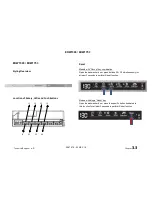
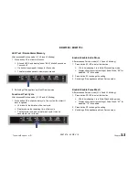
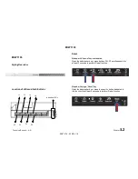
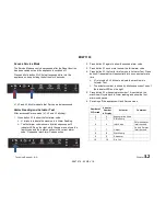
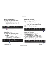
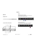
LED Test / Delete Alarm Memory 

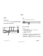
After accessed Service mode (L1, L2 and L3 blinking): 

1.  Press button S2 to start this function. 

  All used LEDS and display (show “8:88”) blinks 5 second on 

1 second off. 

  If a buzzer is equipped, it beeps for 5 seconds. 

  The alarm codes saved in memory are erased.  


2.  Switching off the appliance will exit Service mode. 

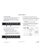
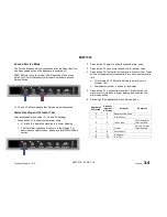
Functional Test Cycle 

After accessed Service mode (L1, L2 and L3 blinking): 

1.  Press button S3 to start the test cycle. The cycle will not start if 

door is opened. 

  L3 blinks for the duration of the test cycle. 

  Display shows the remaining time of test cycle. 

  The test cycle runs as a normal wash cycle. It can be 

cancelled or run to its end. 


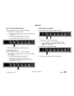
Enable/disable Extra Rinse 

After accessed Service mode (L1, L2 and L3 blinking): 

1.  Press button S1+S2 to enter this function. 

  L1 blinks indicating it is in Extra Rinse setting mode. 

  Display show the current setting of Extra Rinse. “0E” for 

disabled, “1E” for enabled. 

2.  Press button S1 to change the setting. 

3.  Switching off the appliance will exit Service mode. 


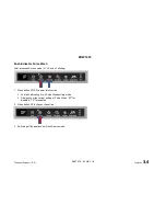
Enable/disable Pulse Wash 

After accessed Service mode (L1, L2 and L3 blinking): 

1.  Press button S2+S3 to enter this function. 

  L2 blinks indicating it is in Pulse Wash setting mode. 

  Display show the current setting of Pulse Wash. “0P” for 

disabled, “1P” for enabled 

2.  Press button S2 to change the setting 

3.  Switching off the appliance will exit Service mode. 


Technical Support – A.R.  


Chapter  

3.3


599 79 76 - 53 REV 1.0

Summary of Contents for EDW 1103

Page 1: ...with electronic control system ELECTROLUX HOME PRODUCTS Customer Care EMEA Training and Operations Support Technical Support Publication number 599 79 76 53 Edition 05 2017 Rev 1 0 EN EDW 503 EDW 1103 EDW 1503 EDW 1753 EDW 1953 EDW 4013 EDW 4033 599 79 76 53 REV 1 0 ...

Page 2: ...ic family Abbreviations Acronyms and Definitions RTA Remaining time adaptation MCF Machine Configuration File NTC PB100 DIVA2 MCB ADO Negative Temperature Coefficient resistor New platform for dual BLDC machines Global hydraulic Platform with single BLDC control in separate unit MCB Motor Control Board DIVA2 Auto Door Opener Document Revisions Revision Date Description v0 0 03 2016 Document creati...

Page 3: ...ater Hardness Setting Rinse Aid Level Setting End of Cycle Buzzer Setting Display on Floor Display Colour Setting ADO Setting According to hardware configuration of the dishwasher and marketing requirement User Mode in individual models can be a subset of above functions The User Mode functions are not described in this Service Manual since they are available on the User Manual Service Mode The fu...

Page 4: ...a test cycle It runs as a normal wash cycle It can be cancelled or run to its end Enable disable Extra Rinse An additional cold rinse phase can be added to the cycles to improve wash performance In factory default settings this is disabled Use this function to enable or disable the Extra Rinse Enable disable Pulse Wash Pulse Wash can be disabled from the cycles to improve wash performance In facto...

Page 5: ...his function Access Service Mode 1 Reset 2 Turn off the dishwasher 3 Press and hold S1 while switching on the dishwasher Keep holding the Program button until LED L1 blinks L2 and L3 is on Service mode is accessed 4 Release S1 L1 L2 L3 S1 Indication LEDs Technical Support A R Chapter 3 1 599 79 76 53 REV 1 0 ...

Page 6: ...is in Actuator Test See the table for details of Number of pressing and Actuator Number 5 Press S1 when actuator number 10 is activated the machine will cycle back to Alarm reading and show the first alarm code saved 6 Switch off the appliance to exit Service mode Number of S1 Pressed Actuator Comment 4 Regeneration Valve 5 Drain Pump 6 Inlet Valve Off when water level reached 7 Heater On only if ...

Page 7: ...it till L1 and L2 is turned off then press S1 and close the door The cycle starts and runs the same as a normal cycle LED L3 blinks for the duration of the cycle 3 The cycle and be cancelled or run to its end Enable disable Extra Rinse Not available for this User Interface Enable disable Pulse Wash Not available for this User Interface Technical Support A R Chapter 3 1 599 79 76 53 REV 1 0 ...

Page 8: ...the dishwasher door press buttons S2 S3 simultaneously for at least 2 seconds to perform Reset function Models with single Reset key Open the dishwasher door press the specific button dedicated to this function for at least 2 seconds to perform Reset function S1 S2 S3 L1 L2 L3 L4 S4 Technical Support A R Chapter 3 3 599 79 76 53 REV 1 0 ...

Page 9: ... section 2 Press button S1 again to show the second alarm code 3 Press button S1 once more to show the third alarm code 4 Press button S1 the fourth time to move to Actuator Test Press button S1 repeatedly will sequentially turn on one actuator at a time L1 is turned off L2 blinks to indicate the machine is in Actuator Test The actuator number is shown in the display 5 Press button S1 when actuato...

Page 10: ...runs as a normal wash cycle It can be cancelled or run to its end Enable disable Extra Rinse After accessed Service mode L1 L2 and L3 blinking 1 Press button S1 S2 to enter this function L1 blinks indicating it is in Extra Rinse setting mode Display show the current setting of Extra Rinse 0E for disabled 1E for enabled 2 Press button S1 to change the setting 3 Switching off the appliance will exit...

Page 11: ...press buttons S2 S3 simultaneously for at least 2 seconds to perform Reset function Models with single Reset key Open the dishwasher door press the specific button dedicated to this function for at least 2 seconds to perform Reset function L1 L2 L3 S1 S2 S3 L4 S4 Indication LEDs Technical Support A R Chapter 3 2 599 79 76 53 REV 1 0 ...

Page 12: ...Codes section 2 Press button S1 again to show the second alarm code 3 Press button S1 once more to show the third alarm code 4 Press button S1 the fourth time to move to Actuator Test Press button S1 repeatedly will sequentially turn on one actuator at a time L1 is turned off L2 blinks to indicate the machine is in Actuator Test The actuator number is shown by blink sequences of one of the indicat...

Page 13: ...e disable Extra Rinse After accessed Service mode L1 L2 and L3 blinking 1 Press button S1 S2 to enter this function L1 blinks indicating it is in Extra Rinse setting mode The Extra Rinse setting is shown by one of the indicator LEDs on the right LED off for disabled on for enabled 2 Press button S1 to change the setting 3 Switching off the appliance will exit Service mode Enable disable Pulse Wash...

Page 14: ... dishwasher door press buttons S2 S3 simultaneously for at least 2 seconds to perform Reset function Models with single Reset key Open the dishwasher door press the specific button dedicated to this function for at least 2 seconds to perform Reset function L4 S4 Technical Support A R Chapter 3 4 599 79 76 53 REV 1 0 ...

Page 15: ...ion 2 Press button S1 again to show the second alarm code 3 Press button S1 once more to show the third alarm code 4 Press button S1 the fourth time to move to Actuator Test Press button S1 repeatedly will sequentially turn on one actuator at a time L1 is turned off L2 blinks to indicate the machine is in Actuator Test The actuator number is shown in the display 5 Press button S1 when actuator num...

Page 16: ...rt the test cycle The cycle will not start if door is opened L3 blinks for the duration of the test cycle Display shows the remaining time of test cycle The test cycle runs as a normal wash cycle It can be cancelled or run to its end Enable disable Extra Rinse After accessed Service mode L1 L2 and L3 blinking 1 Press button S1 S2 to enter this function L1 blinks indicating it is in Extra Rinse set...

Page 17: ...3 to enter this function L2 blinks indicating it is in Pulse Wash setting mode Display show the current setting of Pulse Wash 0P for disabled 1P for enabled 2 Press button S2 to change the setting 3 Switching off the appliance will exit Service mode Technical Support A R Chapter 3 4 599 79 76 53 REV 1 0 ...

Page 18: ...m Key for at least 2 seconds and then follow the instructions on the screen to perform Reset function For EDW4033 press the Program Key for at least 2 seconds and then follow the instructions on the screen to perform Reset function Access Service Mode For EDW 4013 press and hold S2 while turn the appliance on keep holding the buttons for 4 seconds For EDW 4033 press and hold S1 while turn the appl...

Page 19: ...nction shown in screen and using OK button to enter the selected function then follow the instruction in the screen to perform the functions Follow the instruction in the screen or switching off the appliance to save the new setting and exit Service mode Technical Support A R Chapter 3 5 599 79 76 53 REV 1 0 ...

Page 20: ...ered The lowest main voltage threshold is 180 Volt If the voltage goes back to over 186 Volt the electronic board cancels the error status and the cycle resumes The i00 alarm is also deleted If the mains voltage continues to exceed the maximum threshold the electronic board does not do anything IMPORTANT the i00 alarm is not stored and cannot therefore be read in Service Mode i10 Code family Water...

Page 21: ...r the winding in the pump is open circuit Acoustic signal and visual alarm depending on the appliance customization the program is restarted automatically in this alarm condition If this alarm condition occurs the drain pump is activated Time limit set 10 sec i40 Codes family Analogue pressure sensor problem i41 code No pressure sensor signal The error is set if the sensor signal is lost for more ...

Page 22: ...is detected during start of motor and also during the running motor reasons can be dirt too high load mechanical problems on impeller i55 code DCLink undervoltage Alarm is set when the Vbat voltage on motorcontrolboard will be detected lower than 225 VDC and will be cleared if voltage is greater than 260 V DC i56 code DCLink overvoltage Alarm is set when the DCLink voltage on power controlboard is...

Page 23: ... alarm is reset by MCB after verification procedure with baseboard PB100 specific Alarm is set if load is 0 68 A for 10 s for the wash pump or 0 55 A for 10 s for the drain pump i5B i5H code WP DP current plausibility Alarm is set if currents are not changing within 2 5 s with less than 0 0275 A for WP Alarm is set if currents are not changing within 0 5 s with less than 0 03363 A for DP B may be ...

Page 24: ...d to heater i70 Code family Thermistor problem i70 code NTC sensor value out of range The alarm is stored and displayed only in service mode the washing program continues without the activation of the heating element Monitoring starts immediately after the program has been started The voltage measured at the ends of the NTC must be between 0 04 and 4 7 V Time limit set 10 sec i80 Code family Auto ...

Page 25: ...ignalled if the configuration control of the UI configuration data provided erroneous results i94 code UIDATA version mismatch The alarm is signalled if the UIDATA provided in configuration file mismatches the attached UI board i95 code UIDATA checksum mismatch The alarm is signalled if the UIDATA checksum type provided in configuration file mismatches with the attached UI board iB0 iH0 Code famil...

Page 26: ...ng the calibration could be because the sensor is broken The washing program will run as though the dirt value to be considered is high iB4 iH4 code turbidity sensor too noisy calibration error The alarm is set if the turbidity readings are too noisy during calibration could be because of dirt or air bubbles disturbing the turbidity sensor during calibration The washing program will run as though ...

Page 27: ...ime o If the flow controller is not moving at all or if the sensor is broken or shorted the timeout is 12 seconds o If the flow controller is indeed moving but cannot find the position the overall timeout is up to about 110 seconds If the alarm is signalled then heating element is deactivated as long as the alarm is active iF0 Code family water level problem iF0 Code overfilling detected The alarm...

Page 28: ... i44 i44 Cycle will be terminated electronic stop after on off or failure solved electronic will switched to reset on condition i40 Pressure Sensor Calibration signal too low warning No Nothing i45 Old calibration will be used cycle continues Nothing Pressure Sensor Calibration warning No Nothing i46 Old calibration will be used cycle continues Nothing 50 AC Wash pump tsc abort Yes i51 i51 Cycle w...

Page 29: ...ly DP BLDC motor not connected abort Yes i5F i5F Cycle will be terminated and electronic switched to reset on condition i50 60 Heating problem warning No Nothing i60 Heating element will be switched off for the rest of the cycle Nothing Heating over temperature abort No i61 i61 Cycle will be terminated and electronic switched to reset on condition i60 Heater relay problems abort No i62 i62 Heating...

Page 30: ...to be considered is high Nothing PB100 after P100R230 PB101 and PB150 sensor too noisy calibration warning No Nothing ib4 iH4 Cycle continues as though the dirt value to be considered is high Nothing C0 No user interface detected stop No Nothing ic0 Cycle stop and continuous automatic if problem solved Nothing Macs bus communication stop Yes iC1 ic1 Macs low level communication Cycle stop and cont...

Reviews: