INSTALLATION & SETUP
VistaPro 2000 User's Manual
2-11
Optional interface modules allow you to increase the total number of inputs and
to accommodate other signal types. These modules may be installed in the upper
left section of the control panel on the rear of the VistaPro 2000 (Dat 2). They
are:
•
RGB Input Module
•
RGB Loop Thru Module
•
Composite/S-Video Module
•
HDTV Input Module
•
PC Analog Input Module
NOTES: 1) Installation of optional interfaces must be done by qualified service
personnel only — contact your dealer or Electrohome. 2) See Appendix E,
Optional Input Modules for a brief description of each interface.
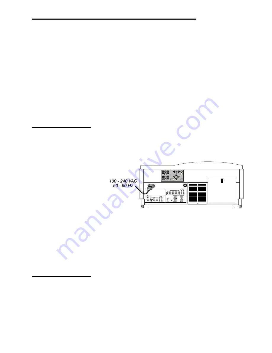
Plug the special notched AC line cord (power cord) into the line input socket
located at the left rear of the projector (Figure 2.12). Plug the three-prong end of
the line cord in a grounded AC outlet. Input voltage to the projector must be
between 100 and 240 VAC, 50 or 60 Hz. The power source must be capable of
supplying 1080 watts of power to the projector.
Figure 2.12. Power Connection
WARNING:
Do not attempt operation if the AC input is not within
the specified input range.
Caution: Once the projector is turned off, the lamp cooling fans will continue to
run for approximately five minutes to ensure that the projector and lamp have
sufficiently cooled, at which point the fans will automatically shut off. To avoid
damaging the projector, never unplug the line cord while the lamp cooling fans
are running. Do not unplug the projector in order to power down.
VistaPro 2000 is set up at the factory for use in a front screen, floor mount
orientation. If the installation is ceiling mount or rear screen, you may notice that
displayed images are upside down and/or reversed. To correct, you must change
the image orientation from within the Preferences menu. You may prefer to do
this before physically installing the projector, however it can be done at any
time. See Section 3, Operation for further information.
Other inputs
'
2.5
Power
Connection
2.6
Operating
Orientation


