background image

29

05/2005 - Art. Nr. 13 018 106A

Overview

Important instructions

Important instructions

The burners VECTRON GL 05.700
DUO PLUS and VECTRON GL
05.1000 DUO PLUS are designed to
burn Category II 2 ELL 3P natural or
propane gas and designed for the
combustion of extra-light fuel-oil
according to countries :
A : ÖNORM C1109: standard or

low-sulphur

BE: NBN T52.716: Fuel oil standard

NBN or EN590: Low-sulphur

CH : SN 181160-2 Extra-Light fuel-oil

and Eco-fuel-oil low sulphur

DE : DIN 51 603-1 standard and

low-sulphur.

The special construction of the burner
head with internal recirculation of
exhaust gases means that combustion
is very low in nitric oxide when burning
natural gas. Burner construction and
operation are in compliance with EN
267 and EN 676. Assembly, start-up
and maintenance must be carried out
only by authorized specialists and all
applicable guidelines and regulations
complied with.
Gas pipes and fittings must likewise be
installed in compliance with all
applicable guidelines and regulations
(e.g. DVGW-TRGI 1986/96, TRF 1988,
DIN 4756).
Only DVGW-tested and -approved
sealing materials should be used.
Connections should be leak-tested
using non-corrosive foam-producing or
similar materials.
Gas piping should be vented before
start-up. Under no circumstances
should venting be carried out over the
furnace.
Repair work to switches, limiters,
control and safety units and other
individual items of safety equipment
must be carried out by the relevant
manufacturer or his representatives.
The replacement of original parts must
be carried out by specialist staff.

Basic regulations

To ensure the safe, environmentally
correct and energy-saving operation of
the system, the following standards
must be complied with:

DIN 4705
Calculation of flue dimensions.
DIN 4755
Oil-fired systems.
EN 267
Forced-draught gas burners.
EN 676
Forced-draught gas burners
EN 226
Connection of forced-draught
atomising oil and gas burners to heat
generators
VDE 0116
Electrical equipment for firing systems
EN 60335-1
Safety of electrical equipment for
domestic use and similar purposes
VDE 0722
Electrical equipment for non-electrically
heated heating units.

Installation location

The burner must not be started up in
areas containing aggressive fumes
(e.g. hair spray, perchloroethylene,
carbon tetrachloride), heavy
accumulations of dust or high
atmospheric humidity (e.g. laundries).
An air inlet must be present: :

up to 50 kW: 150 cm²

per additional kW: +2 cm²

Variations may arise as a result of local
regulations.

The guarantee does not cover
damage resulting from:

Inappropriate use.

Incorrect assembly or repair by
purchasers or third parties, including
the use of parts from outside
manufacturers.

Operation of the system at
excessive pressure.

Final delivery and instructions for
use

The firing system manufacturer must
supply the operator with operating and
maintenance instructions on or before
final delivery. These should be clearly
displayed in the area in which the heat
generator is installed. The address and
telephone number of the nearest
after-sales service agent is to be
entered.

Notes for the operator

The system should be inspected by a
specialist at least once a year. It is
strongly recommended to take out a
service contract to guarantee regular
servicing.

EN

Summary of Contents for VECTRON GL 05.1000 DUO PLUS

Page 1: ...Zweistoffbrenner 2 26 DE EN Ersatzteilliste Spare parts list Pièces de rechange Wisselstukkenlijst 13 018 108 Elektro und Hydraulikschema Electric and hydraulic diagrams Schémas électrique et hydraulique Elektrische en hydraulische schema 13 018 317 Operating instructions For the authorized specialist Fuel oil Gas dual fuel burners 27 51 ...

Page 2: ...Öldruckregulierung 18 Luftregulierung 19 Voreinstellung Gasarmatur 20 Einregulierung des Brenners 21 22 Wartung 23 24 Störungsbeseitigung 25 26 Konformitätserklärung für Zweistoffbrenner Wir CEB 18 rue des Bûchillons Ville la Grand F 74112 ANNEMASSE Cedex erklären in alleiniger Verantwortung daß die Produkte VECTRON GL 05 700 DUO PLUS VECTRON GL 05 1000 DUO PLUS mit folgenden Normen übereinstimmen...

Page 3: ...ennkopf mit Flanschdichtung und Befestigungsschrauben Gasarmaturengruppe Zubehör auf Wunsch Dichtheitskontrollgerät VPS 504 Manometer Kompensator Prüfbrenner separater Luftansaugkasten Ansaugschalldämpfer Betriebsstundenzähler Öl Gas Universalregler RWF 40 Potentiometer auf Stellmotor Luftdruckwächter mit Prüftasten Ölmengenzähler Übersicht Brennerbeschreibung A1 Feuerungsautomat B10 Messpunkt µA ...

Page 4: ...durch die Fachkraft zulässig Grundsätzliche Bestimmungen Für einen sicheren umweltgerechten und energiesparenden Betrieb berücks ichtigen Sie folgende Normen DIN 4705 Berechnung von Schornsteinabmes sungen DIN 4755 Ölfeuerungsanlagen EN 267 Ölzerstäubungsbrenner EN 676 Gasbrenner mit Gebläse EN 226 Anschluß von Ölzerstäubungs und Gasbrennern mit Gebläse am Wär meerzeuger VDE 0116 Elektrische Ausrü...

Page 5: ...eichen 1312 AQ 0924 Das Regelverhältnis ist ein mittlerer Wert und kann je nach Anlagenauslegung variieren Arbeitsfeld Bei der Brennerauswahl ist der Kesselwirkungsgrad zu berücksichti gen Das Arbeitsfeld zeigt die Brennerleistung in Abhängigkeit vom Feuerraumdruck Es entspricht den Maximalwerten nach EN676 bzw EN267 gemessen am Prüfflammenrohr Berechnung der Brennerleistung QF Brennerleistung kW ...

Page 6: ...ung 3 8 i M16x1 5i 1500 mm Gewicht kg 60 CE Zeichen 1312 AQ 0925 Das Regelverhältnis ist ein mittlerer Wert und kann je nach Anlagenauslegung variieren daPa mbar kW 850 520 240 620 740 0 20 40 60 80 100 100 300 500 700 900 0 2 4 6 8 10 daPa mbar kW 520 240 0 20 40 60 80 100 200 400 600 800 1000 0 2 4 6 8 10 daPa mbar kW 520 240 0 20 40 60 80 100 200 400 600 800 1000 0 2 4 6 8 10 daPa mbar kW 850 5...

Page 7: ...ände Für Servicearbeiten ist ein freier Abstand von min 0 6 m auf jeder Seite des Brenners sicherzustellen Gasarmaturgruppe Montage sowohl links als auch rechts möglich MBVEF 420 Rp2 Übersicht Maßbild VECTRON GL 05 700 1000 DUO PLUS mit Gasarmatur MBVEF 412 und MBVEF 420 ...

Page 8: ... Abstände Für Servicearbeiten ist ein freier Abstand von min 0 6 m auf jeder Seite des Brenners sicherzustellen Gasarmaturgruppe Montage sowohl links als auch rechts möglich Übersicht Maßbild VECTRON GL 05 700 1000 DUO PLUS mit Gasarmatur VGG 10 Rp2 ...

Page 9: ...N65 Abstände Für Servicearbeiten ist ein freier Abstand von min 0 6m auf jeder Seite des Brenners sicherzustellen Gasarmaturgruppe Montage sowohl links als auch rechts möglich Übersicht Maßbild VECTRON GL 05 1000 DUO PLUS mit Gasarmatur VGF 10 DN65 ...

Page 10: ...ter beidseitig 6 Filter unter Deckel 7 Typenschild 8 Anschluß Luftdruckleitung pL R1 8 9 Einstellschraube für Verhältnis V 10 Druckmeßnippel pe vor Ventil 1 beidseitig 11 Gasdruckmeßnippel M4 nach Ventil 2 12 Einstellschraube Nullstellung N 13 Anschluß Feuerraumdruckleitung pF R1 8 14 Anschluß Gasdruckleitung pG R1 8 15 Ausgangsflansch 16 Druckmeßnippel pa nach Ventil 1 beidseitig 17 Betriebsanzei...

Page 11: ...Klipse vor die entsprechenden Öffnungen stellen und eindrücken Option Betriebsstundenzähler für Öl und Gas Anschlußkabel bereits verdrah tet Dreipunktschrittregler RWF40 in genormter Einbaustelle Funktion der Schalter A Brennstoffwahl vor Ort über Schalter C D B Brennstoffwahl über Fernsteue rung C Brennstoff Öl D Brennstoff Gas E Betriebsart Manuell F Betriebsart Automatisch G manuelle Erhöhung d...

Page 12: ...szeit Öffnung der Luftklappe auf Kleinlast Gas Nocke V Beginn des Regelbetriebes Brennstoffvorwahl Öl Nach Ablauf der Vorspülzeit wird die Luftklappe in Zündstellung Öl gefahren Nocke IV wird die Zündung zugeschaltet Magnetventil Y1 Stufe 1 geöffnet Brennerstart in Stufe 1 Nach Regelfreigabe Öffnung der Luftklappe auf Kleinlast Öl Nocke VI Umschalten auf Vollast Öl Bei Anforderung der Leistungsstu...

Page 13: ...13 05 2005 Art Nr 13 018 106A Übersicht Hydraulikschema ...

Page 14: ...nkrecht über der Gas armatur liegen Die mitgelieferten gekennzeichneten Impulsleitungen pF pL und pG für linken oder rechten Gasanschluß montieren Bei SKP 70 das mitgelieferte Sicher heitsmagnetventil Bausatz mit Spule nach oben montieren den mit gelieferten Gasfilter Bausatz waage recht mit obenliegendem Deckel 2 Messanschlüsse einbauen Den mitgelieferten Gaskugelhahn Bausatz vor dem Gasfilter mo...

Page 15: ...achse muß das kpl Düsengestänge um 180 gedreht werden Der selbe Sachverhalt ergibt sich bei Gasan schluß rechts und Brennergehäuse über der Brennkopfachse Dazu Stau scheibe abmontieren Schraube A herausdrehen Düsengestänge um 180 drehen und wieder einbauen Düsengröße überprüfen falls erforder lich gemäß Tab S 18 austauschen Einstellung der Zündelektroden und der Stauscheibe überprüfen und justiere...

Page 16: ...en Der selbe Sachverhalt ergibt sich bei Gasan schluß rechts und Brennergehäuse über der Brennkopfachse Dazu Stau scheibe abmontieren Schraube A herausdrehen Düsengestänge um 180 drehen und wieder einbauen Düsengröße überprüfen falls erforder lich gemäß Tab S 18 austauschen Einstellung der Zündelektroden und der Stauscheibe überprüfen und justieren Montage Mischeinrichtung UV Zelle 1 herausziehen ...

Page 17: ...schema verdrahtet werden Die elektrische Verbindung zwischen Brenner und Gasarmatur erfolgt über die vorgesehenen Stecker Prüfung vor Inbetriebnahme Brenner vom Stromnetz trennen und spannungsfrei machen Öl und Gasventile schließen Betriebsvorschriften der Wärmeer zeuger und Regelunghersteller zur Kenntnis nehmen Prüfen ob Gasart Gasdruck dem Brenner entsprechen Dichtheit der Gasleitung Entlüftung...

Page 18: ... anla genbedingte Korrekturen notwendig sein Günstige Verbrennungswerte sind unter Verwendung der Düsen Danfoss 45 B vom Werk empfohlen zu erreichen Gleichwertige Düsen Delavan 45 A Steinen 60 SS Danfoss 60 B für 1 Stufe Gasdruckwächter Durchsichtigen Deckel ablegen Die Einstellung erfolgt über eine drehbare Einstellskala und einen Index x Provisorisch auf den Minimalwert der Skala einstellen Luft...

Page 19: ...asbetrieb besteht die Möglich keit die Zündlast Nocke III über oder unter der Kleinlast Nocke V einzustellen Bei Ölbetrieb sollte die Zündlast Nocke IV und die Kleinlast Nocke VI gleichgestellt werden Bei Ölbetrieb muß die Umstellung auf die Zwischenstufe Nocke VII unter der Umschaltung zur Drucks tufe 2 Nocke VIII und über der Kleinlast Öl Nocke VI eingestellt werden Die Umschaltung zur Druckstuf...

Page 20: ... Anschluß Feuerraumdruckleitung pF R1 8 14 Anschluß Gasdruckleitung pG R1 8 15 Ausgangsflansch 16 Druckmeßnippel pa nach Ventil 1 beidseitig 17 Betriebsanzeige Ventile V1 V2 Option 18 Impulsleitungen Einstell Index des Verhältnis ses R Anzeige der Gasventilöffnung Einstell Index des D Wertes Gasventil SKP pBr pG Impulsleitung Gas pF Impulsleitung Feuerraum pL Impulsleitung Luft D Einstellschraube ...

Page 21: ...er Taste G festlegen Dazu ist die Nocke V je nach Bedarf nachzujus tieren Abgaswerte nochmals kontrollieren und je nach Messwert das Gas Luft Verhältnis nachjustieren Brenner wieder auf Großlast bringen die Verbrennungswerte kon trollieren Haben sich die Meßwerte durch Ver stellen der Schraube D beim SKP Regler oder der Schraube N beim MBVEF Ventil geändert müssen beim SKP Regler das Ver hältnis R...

Page 22: ...Die Verbrennungswerte kontrollieren Rußtest CO2 Um den CO2 Wert einzustellen ist der Pumpendruck an der Druck einstellung 6 2 zu justieren Ist die Inbetriebnahme bei Gasbe trieb durchgeführt darf die Nocke I bei der Inbetriebnahme Öl nicht mehr verstellt werden Muß das Maß Y der Brennkopfeinstellung geändert werden so ist der ganze Ein stellvorgang nochmals vorzunehmen Einstellung Zündlast Nocke I...

Page 23: ...gen ohne die Druckabnahmeleitung des Differential Luftdruckwächters zu beschädigen Die Luftdruck Leitungen trocken reinigen Kein Druckmedium verwenden Die 4 Befestigungsschrauben des Luftleitschnabels entfernen Luftkanal und Lüfterrad gründlich reinigen Wieder zusammenbauen Servicearbeiten an Kessel und Brenner führt ausschließlich die geschulte Fachkraft durch Um eine turnusgemäße Durchführung de...

Page 24: ...en Raum zwischen Flammrohr und Türisolierung mit feuerfestem Material auskleiden Achtung Feuerraumdruckabnahmeleitung darf dabei nicht verstopft werden In umgekehrter Reihenfolge wieder einbauen Variante 2 Demontage des Brenners Zünd Mischeinrichtung demontieren Gasarmaturgruppe demontieren Druckabnahmerohre abschrauben Elektroanschlüsse lösen Gasanschluß abschrauben 4 Muttern M10 Brennergehäuse l...

Page 25: ...ter defekt oder falsch eingestellt Luftdruckwächter ersetzen Schütze entriegeln justieren oder austauschen Schalter austauschen Verdrahtung kontrollieren Motor austauschen Luftdruckwächter justieren oder austauschen z Programmsymbol Störung im Flammenüberwachungskreis Flammenwächter reinigen Feuerungsautomat austauschen 1 1 x oder v Programmsymbol 1 keine Zündung Ventile öffnen nicht Flammenkopf F...

Page 26: ...as Brennkopf verstellt Stellantrieb defekt mechanische Klemmung der Luftklappe mechanische Kupplung defekt Fremdlicht beim Start Abnutzung der UV Zelle Dichtheit der Ölventile prüfen Nachbelüftung Funktion prüfe Luftdruckwächter ersetzen Schützschalter entriegeln einstellen oder ersetzen Schütz ersetzen Kabelverbindungen prüfen Motor ersetzen Luftdruckwächter einstellen oder ersetzen Druckleitunge...

Page 27: ...il pressure 18 Regulating the air supply 19 Initial setting of gas valve assembly 20 Regulating the burner 21 22 Maintenance 23 24 Troubleshooting 25 26 Declaration of conformity for dual fuel burners We CEB 18 rue des Bûchillons Ville la Grand F 74106 ANNEMASSE Cedex declare under our sole responsibility that the products VECTRON GL 05 700 DUO PLUS VECTRON GL 05 1000 DUO PLUS are in conformity wi...

Page 28: ...and securing screws Gas valve assembly module Optional accessories leakage test device VPS504 manometer compensator test burner separate air intake box suction intake noise absorber oil gas running time meter RWF 40 universal regulator potentiometer on servomotor air pressure switch with test button oil volume meter Overview Burner description A1 control and safety unit B10 measure point µA DC F6 ...

Page 29: ...ts must be carried out by specialist staff Basic regulations To ensure the safe environmentally correct and energy saving operation of the system the following standards must be complied with DIN 4705 Calculation of flue dimensions DIN 4755 Oil fired systems EN 267 Forced draught gas burners EN 676 Forced draught gas burners EN 226 Connection of forced draught atomising oil and gas burners to heat...

Page 30: ...5i 1500 mm Weight kg 60 CE Mark 1312 AQ 0924 The control ratio is a medium value and may change according to installation conditions Power graph Boiler efficiency should be taken into consideration when selecting the burner Power graph indicates burner power dependent on furnace pressure It corresponds to the maximum values according to EN 676 or EN 267 measured at the test blast tube Calculation ...

Page 31: ...8 5 45 B Flexible hoses 3 8 i M16x1 5i 1500 mm Weight kg 60 CE Mark 1312 AQ 0925 The control ratio is a medium value and may change according to installation conditions daPa mbar kW 850 520 240 620 740 0 20 40 60 80 100 100 300 500 700 900 0 2 4 6 8 10 daPa mbar kW 520 240 0 20 40 60 80 100 200 400 600 800 1000 0 2 4 6 8 10 daPa mbar kW 520 240 0 20 40 60 80 100 200 400 600 800 1000 0 2 4 6 8 10 d...

Page 32: ...ere should be a space of no less than 0 6 m on each side of the burner for maintenance purposes Gas valve assembly The valve assembly can be fitted on the left or the right MBVEF 420 Rp2 Overview Scale diagram VECTRON GL 05 700 1000 DUO PLUS with MBVEF 412 and MBVEF 420 gas valve assembly ...

Page 33: ...here should be a space of no less than 0 60 meter on each side of the burner for maintenance purposes Gas valve assembly The valve assembly can be fitted on the left or the right Overview Scale diagram VECTRON GL 05 700 1000 DUO PLUS with VGG 10 Rp2 gas valve assembly EN ...

Page 34: ...ts There should be a space of no less than 0 60 meter on each side of the burner for maintenance purposes Gas valve assembly The valve assembly can be fitted on the left or the right Overview Scale diagram VECTRON GL 05 1000 DUO PLUS with VGF 10 DN65 gas valve assembly ...

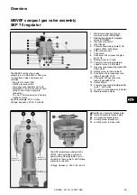
Page 35: ...8 Connection for air pressure pipe pL R 1 8 9 Setting screw for V ratio 10 Pressure measuring nipple pe ahead of valve 1 both sides 11 Gas pressure measuring nipple M4 after valve 2 12 Setting screw for zero value N 13 Connection for furnace pressure take off pipe pF R 1 8 14 Connection for gas pressure take off pipe pG R 1 8 15 Output flange 16 Pressure measuring nipple pa after valve 1 both side...

Page 36: ...t the appropriate openings and push in Option oil and gas running time meters connection cables already wired up RWF 40 three point regulator fitted at standardized position Purpose of switches A on site fuel selection via switch C D B fuel selection by remote control C Fuel oil D Gas E manual operation F automatic operation G increases gas power manually decreases gas power manually H 1 oil low l...

Page 37: ...ety time air flap is opened to low load gas cam V control operation starts Oil fuel selected At end of initial circulation time air flap is moved to oil ignition position cam IV ignition is closed magnetic valve Y1 Stage 1 is opened burner starts up Stage 1 after control system release air flap is opened to low load fuel oil cam VI Changing over to high load fuel oil When power stage 2 is requeste...

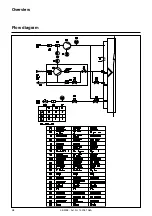
Page 38: ...05 2005 Art Nr 13 018 106A 38 Overview Flow diagram ...

Page 39: ...ositioned vertically above the gas valve assembly Mount the supplied and marked pressure release pipes pF pL and pG for gas connection on the left or right For SKP 70 fit the supplied magnetic safety valve assembly with the solenoid upwards and the supplied gas filter assembly horizontally with the cover on top side with 2 measurement connections Mount the gas shut off valve assembly ahead of the ...

Page 40: ...must be rotated through 180 The same applies if the gas connection is on the right and the burner housing above the axis of the burner head To do so remove the turbulator Unscrew screw A completely Rotate the nozzle arm through 180 and refit Check the nozzle size replace if necessary in accordance with the table on p 42 Check and adjust the position of the ignition electrodes and the turbulator Fi...

Page 41: ...gas connection is on the right and the burner housing above the axis of the burner head To do so remove the turbulator Unscrew screw A completely Rotate the nozzle line through 180 and refit Check the nozzle size replace if necessary in accordance with the table on p 42 Check and adjust the position of the ignition electrodes and the turbulator Fitting the mixing unit Withdraw UV cell 1 Release an...

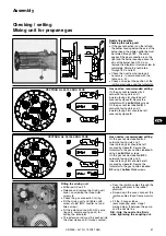
Page 42: ...al diagram Plugs are provided for the power connection between the burner and the gas valve assembly Pre start up check Disconnect the burner by unplugging it from the power supply Close the oil and gas valves Take note of the operating instructions provided by the heat generator and control system manufacturers Check that the gas type and gas pressure are appropriate to the burner Check the gas p...

Page 43: ...ully in each case System specific corrections may be necessary Good combustion values can be achieved using Danfoss 45 B recommended nozzles Equivalent nozzles Delavan 45 A Steinen 60 SS Danfoss 60 B for Stage 1 Gas pressure switch Remove the transparent cover To set use the rotating scale and x marker Provisionally set to the minimum value on the scale Air pressure switch The device contains a mo...

Page 44: ...settings When operating with gas the ignition load cam III setting can be above or below the low load cam V setting When operating with oil ignition load cam IV and low load cam VI should have the same settings When operating with oil changeover to the intermediate load cam VII should be set below changeover to pressure stage 2 cam VIII and above the low load oil cam VI setting The setting for cha...

Page 45: ...w for zero excess air value N 13 Connection for furnace pressure pipe pF R 1 8 14 Connection for gas pressure pipe pG R 1 8 15 Output flange 16 Pressure measuring nipple pa after valve 1 both sides 17 Valve V1 and V2 operation indicator option 18 Pressure release pipes R ratio indicator Gas valve opening indicator D value indicator SKP gas valve pBr pG gas pressure release pipe pF furnace pressure...

Page 46: ...w N of the MBVEF regulator Set the required intermediate load using switch G and re adjust cam V as necessary Check the waste gas values again and re adjust the gas air ratio according to the measurement values Return the burner to high load check the combustion values If the measurement values have changed as a result of adjusting screw D of the SKP regulator or screw N of the MBVEF valve ratio R...

Page 47: ...t Setting the high load Set switch H to 2 Servomotor opens to high load setting Check the combustion values soot test CO2 To set the CO2 value adjust the pump pressure via pressure regulator 6 2 If start up has been carried out running on gas do not adjust cam I on start up with oil If the burner head setting dimension Y needs to be altered the whole setting procedure must be carried out again Set...

Page 48: ...the motor panel Remove the panel and motor taking care not to damage the pressure take off pipe of the differential air pressure switch Dry clean the air pressure pipes Do not use pressurized materials Take out the 4 screws securing the air guiding piece Thoroughly clean the air duct and fan Re assemble Burner and boiler servicing can only carried out by a trained specialist The system operator is...

Page 49: ...ce between the blast tube and the door insulation in fire resistant material N B Take care not to obstruct the furnace pressure release pipe Re assemble in reverse order Variant 2 Dismantling the burner Dismantle the ignition and mixing unit Dismantle the gas valve assembly module Unscrew the pressure release pipes Undo the power connections Unscrew the gas connection four M10 nuts Unscrew and rem...

Page 50: ...otor Motor defective Air pressure switch defective or wrongly set Replace air pressure switch Unlock reset or replace protection devices Replace switch Check the wiring Replace the motor Reset or replace air pressure switch z Programme symbol Fault in flame monitoring system Clean flame monitor Replace control and safety unit 1 1 x oder v Programme symbol 1 No ignition Valves do not open Flame hea...

Page 51: ...uited Valve jammed Fuel does not reach burner Too much air and or gas Burner head wrongly set Servomotor defective Air flap jammed Mechanical coupling defective Parasitic flame at start up Wear of UV cell Check oil valves for leaks Check reventilation function Replace air pressure switch Unlock reset or replace protection switches Replace protection device Check cable connections Replace motor Res...

Page 52: ...00 7324 Vilters 0848 808 808 ELCO GmbH Dreieichstr 10 64546 Mörfelden Walldorf 0180 3526180 ELCO France 18 rue des Buchillons 74106 Annemasse 0450877624 ELCO Rendamax B V Amsterdamsestraatweg 27 1410 AB Naarden 035 6957350 AT BE CH DE FR NL Fabriqué en EU Made in EU Hergestellt in der EU Gefabriceerd in de EU Document non contractuel Non contractual document Angaben ohne Gewähr Niet contractueel d...

Reviews: