05/2005 - Art. Nr. 13 018 106A
42
Oil supply
·
The oil burner pump used is a
self-priming gear pump, which must
be connected as two-line pump via a
bleed filter.
·
Systems with a suction intake for EL
fuel-oil must be designed and
dimensioned in accordance with
VSO guidelines (see Eco brochure,
Item No. 12002182).
·
Connect the supplied hoses to the
oil pump (oil hoses can be passed
through the top or bottom aperture
of the housing, as required).
·
The oil hoses should be fitted so
that the burner can be dismantled
without undoing the flexible piping.
·
The oil hoses are connected to the
oil filter with an R3/8" or R1/2"
connection (R3/8"/R1/2" nipple
included).
·
With cube-shaped tanks, the pump
intake line is run up to 5 cm above
the tank bottom, with cylindrical
tanks up to 10 cm above the tank
bottom.
Power supply
The burner and the control system
must be connected in accordance with
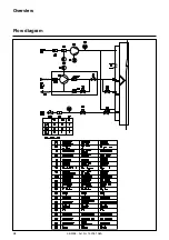
the corresponding circuit diagram.
The power supply and electrical
connections must conform to the
current standards.
The burner is delivered for a 400 V - 50
Hz three-phase mains supply with
neutral wire and earth.
All control unit cables are fitted with
4/7-pole socket components.
The connection cable for the burner
motor must be run through the cable
fittings and wired to the terminal strip as
indicated in the electrical diagram.
Plugs are provided for the power
connection between the burner and the
gas valve assembly.
Pre-start-up check
·
Disconnect the burner by unplugging
it from the power supply.
·
Close the oil and gas valves.
·
Take note of the operating
instructions provided by the heat
generator and control system
manufacturers.
·
Check that the gas type and gas
pressure are appropriate to the
burner.
·
Check the gas pipe for leaks.
·
Vent the fuel supply pipes.
·
Check that the fresh air supply and
exhaust flues are appropriate to the
capacity of the burner.
·
Water pressure in heating circuit,
·
Circulation pump running,
·
Mixer open,
·
Draught regulator in the chimney
opens
·
Power supply in order,
·
Oil level in tank,
·
Oil hoses (feed/return) properly
connected,
·
Oil line connections between the
burner and the tank do not leak,
·
Thermostat settings,
·
Blower motor turns in right direction
(arrow on burner housing),
Gas supply: general provisions
·
Connection of the gas valve
assembly to the gas mains must be
carried out by a recognized
specialist.
·
The gas pipe diameter must be such
that the gas flow is not below the
prescribed pressure.
Burner start-up automatically implies
acceptance of the system. This is the
responsibility of the installer or his
representative as he alone can
guarantee that the system conforms to
the current standards and regulations.
The installer must hold a licence issued
by the gas authority, must have
checked the system for leaks and must
have vented it.
Assembly
Oil supply
Gas supply
Power supply


