05/2005 - Art. Nr. 13 018 106A
46
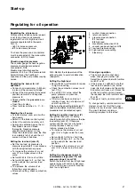
Regulating the burner for gas
operation
·
Open the gas shut-off valve.
·
Set the gas pressure switch and air
pressure switch to minimum values.
·
Connect a microammeter (0-500 µA)
in place of the measuring bridge
(check polarity).
·
Press tumbler switches A - D - E.
·
Switch on the boiler control system.
·
Unlock the control and safety unit.
·
Once there is a flame, check the
combustion values (CO, CO
2
).
·
Read the UV current (permissible
value between 200 and 500 µA).
·
Read the gas flow from the gas
meter.
·
Increase power to high load by
pressing on the + of switch
G
.
·
Check the waste gas values. Adjust
the gas/air ratio according to the
measurement values:
–
for SKP, turn setting screw
R
(remove top cover): + direction to
increase CO
2
, - direction to
decrease CO
2
(see symbols on
upper face of SKP, page 43
–
for MBVEF valve, turn screw
V
:
higher value on scale to increase
CO
2
, lower value on scale to
decrease CO
2
(see page 43)
·
To achieve the required level of
efficiency, maintain the CO
2
values
and waste gas temperatures
specified by the boiler manufacturer.
·
Read the UV current (permissible
value between 200 and 500 µA).
·
Read gas flow-rate at the meter.
·
Set the burner to minimum load and
check the combustion values.
According to the measurement
values, adjust screw
D
of the SKP
regulator, screw
N
of the MBVEF
regulator.
·
Set the required intermediate load
using switch
G
and re-adjust cam
V
as necessary.
·
Check the waste gas values again
and re-adjust the gas/air ratio
according to the measurement
values.
·
Return the burner to high load;
check the combustion values.
·
If the measurement values have
changed as a result of adjusting
screw
D
of the SKP regulator or
screw
N
of the MBVEF valve, ratio
R
must be altered on the SKP
regulator, ratio
V
on the MBVEF
valve, in the appropriate direction.
·
If the burner head setting
(dimension
Y
) needs to be altered,
the whole setting procedure must be
carried out again.
If the combustion values are correct,
proceed as follows for low load and
high load:
·
Adjust the gas flows by altering
servomotor cams V and I.
·
Check the gas flows at the gas
meter.
Setting the ignition load
·
The ignition load setting for gas
operation (cam III) should ensure
that the burner ignites correctly. It
can be below or above the low load
setting.
Setting the gas pressure switch
·
Set the switch to the minimum input
pressure.
·
Slowly close the gas shut-off valve.
·
The burner should switch off
because of lack of gas pressure.
·
Re-open the gas shut-off valve.
Setting the air pressure switch
·
Once the burner is again burning at
low load, determine the shut-off
point of the air pressure switch by
turning the scale disk.
·
Set the air pressure switch 10%
below this shut-off value.
Start-up
Regulating for gas operation
Setting the gas pressure switch and air pressure switch


