39
05/2005 - Art. Nr. 13 018 106A
Assembly
Burner head
Gas valve assembly
Mixing unit, burner housing
Fitting the burner head
·
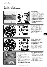
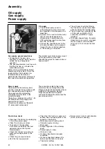
Prepare the burner plate / boiler
door as indicated in the
accompanying diagram.
·
Select an inside diameter of
between 172 and 195 mm; if the
inside diameter is < 195, a notch
must be cut on the gas connection
side to take the furnace pressure
release pipe.
·
Four M10 holes (220-260 mm
diameter circle) are required, as
indicated in the accompanying
diagram.
·
Screw M10 stay bolts into the
burner plate / boiler door and add
the insulation. If the bolt circle is
< 260, cut slots to the required size.
·
Attach the burner head to the burner
plate with four M10 hexagonal nuts
so that the gas valve assembly can
be connected on the left or the right.
The space between the blast tube
and the door insulation must be clad
in fire-resistant material
N.B.: Take care not to obstruct the
furnace pressure release pipe, pF.
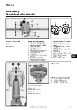
Fitting the SKP70 / MBVEF gas valve
assembly
·
Check that O-ring
B
is properly
seated in gas connection flange
C
.
·
Attach the gas valve assembly with
M10 nuts so that the SKP regulator
or the MBVEF solenoids are
positioned vertically above the gas
valve assembly.
·
Mount the supplied and marked
pressure release pipes
pF
,
pL
and
pG
for gas connection on the left or
right.
·
For SKP 70, fit the supplied
magnetic safety valve (assembly)
with the solenoid upwards and the
supplied gas filter (assembly)
horizontally, with the cover on top
(side with 2 measurement
connections).
·
Mount the gas shut-off valve
(assembly) ahead of the gas filter.
·
For SKP 70, fit the supplied
manometer with pushbutton shut-off
valve (assembly).
·
Mount the leak test device
(accessory).
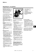
Fitting the burner housing
Dismantle the mixing unit before fitting
the burner housing: undo the fixing
screw (M10 counter nut and Allen
screw) on the side of the unit (opposite
the gas connection) and withdraw the
mixing unit.
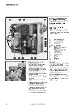
If the burner housing hangs below the
axis of the burner head, proceed as
follows:
·
Unscrew and remove the two lower
nuts on the burner housing and
unscrew the two upper nuts as far
as possible.
·
Place the burner housing sloping
diagonally forwards and fit the two
upper bolts into the two slots in the
burner head flange.
·
Press the burner housing against
the burner head flange and tighten
the 4 nuts.
·
The housing can be mounted above
the axis of the burner head if
required. In this case, the procedure
must be reversed.
No other positions for the burner
housing are possible.
EN

