elco RENDAMAX 30 Operating Instructions Manual Download Page 20

Set up 

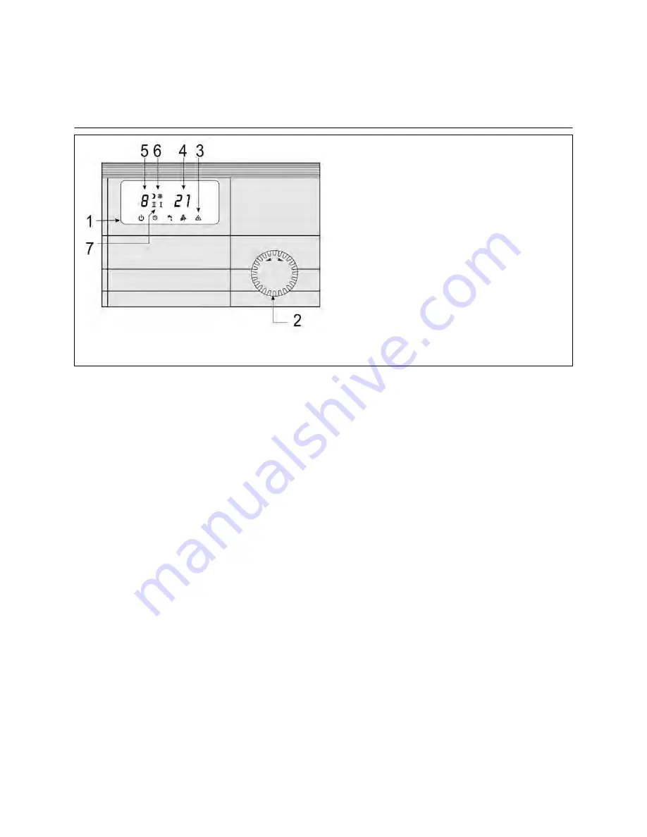
Switch field with operating field KM628  

Operating functions (flap closed) 

When the flap is closed, the desired  
operating status can be selected by  
turning the knob (2) left or right. 

i

Standby 

         Boiler 

not 

in 

use, 

frost 

protection 

active 


q

Automatic operation   


Boiler in use for heating and hot water user  

F

Summer operation 


Boiler in summer operation (only hot water use)  

j

I  Chimney sweep operation, minimum load   

Boiler in use, minimum load  

j

II Chimney sweep operation, maximum load  

Boiler in use, maximum load  

20

1 Operating 

type 


i

 Standby 

q

 Automatic 

operation 

F

 Summer 

operation 

j

  Chimney sweep operation 

Operating type selector  

3 Fault 

display 

E

4 Lead 

temperature 

5 Fault 

code 

(blinking) 

6 Heating 

circuit 

status 

C

 Night 

operation 

B

 Day 

operation 


(Blinking) Burner on 

7 Service 

status 

j

I  Service status minimum burner 

  output 

j

II Service status maximum burner  

  output 

Summary of Contents for RENDAMAX 30

Page 1: ...Operating Instructions only for authorised experts RENDAMAX 30 01 2007 Art No 12 076 446 doc2030 ...

Page 2: ... Air exhaust system 11 Design variations 12 Exhaust systems ambient air dependent 13 Example exhaust system 13 Installing the burner 14 Dismantling assembling the cover 14 Burner connection filling the system 15 Electrical installation 16 Set up Control measures 17 Circulating pump 17 Control measures 18 Gas fitting settings 19 Switch field with operating field KM 628 20 Display in operating field...

Page 3: ... the following Unsuitable or incorrect use or operation Incorrect assembly ot set up by the purchaser or third parties Connection of parts of other origin Operation of the unit with excess pressure or outside the work s performance details Use of incorrect fuel Non compliance with the infor mation in the operating instructions and the labels attached to the burner In Austria the following also app...

Page 4: ...2035 If necessary the water must be softened No chemical anti corrosion substances must be used In Austria ÖNORM H 5195 1 also applies In Switzerland SWKI No 97 1 also applies Unknown water quality and replace ment systems Frequently substances and additives are in hot water which impact on the function and life of the burner Therefore either x heat the old system and then fully empty before repla...

Page 5: ...tion air enters the device through an air infeed system The burner is used for closed hot water heating systems The boiler output is modulated to the current heating requirements by the integrated regulator Heat exchanger The stainless steel heat exchanger is made from flat spirals and ensures a transfer of the exhaust gas s heat to the boiler water The condensation takes place in the upper sectio...

Page 6: ...ir pressure is built up PL 0 the gas valve remains closed The gas air pressure ratio and thus also the gas air volume ratio can be set and then remain almost constant over the set load range Technical data Safety close valve 2 class B C Mains power Type 65 100 AC 24 V Type 120 AC 230 V Power consumption Type 65 100 0 42 A Type 120 0 09 A Gas fitting incl gas filter 1 Operating type i Standby q Aut...

Page 7: ... g s 31 41 46 58 Exhaust gas temperature net TV TR 75 60 C 70 70 70 70 Exhaust gas temperature net TV TR 40 30 C 55 55 55 55 Gas category II2ELL3P II2H3P Exhaust gas value group G61 G61 G61 G61 Construction type Exhaust gas systems B23 C13 C33 C43 C53 C63 C83 All All All All Ionisation flow min P 15 0 15 0 15 0 15 0 Connections Air exhaust gas pipe concentric DN 80 125 110 150 110 150 110 150 Air ...

Page 8: ...mensions Type R30 65 R30 85 R30 100 R30 120 B1 mm 120 140 140 140 D mm 80 100 100 100 D1 mm 80 100 100 100 G R 3 4 R 3 4 R 3 4 R 3 4 L mm 405 510 560 670 L1 mm 90 90 90 90 W R 11 4 Rp 1 R 11 4 Rp 1 R 11 4 Rp 1 R 11 4 Rp 1 8 ...

Page 9: ...n pipes must not be securely installed The condensation is trapped in a funnel and fed into the sewage system Recommendation Accessories neutralisation device Note worksheet ATV A 251 Exhaust pipes Infeed exhaust system The applicable local provisions for the design of the exhaust system must be observed The burner can only be operated with approved exhaust systems On site exhaust systems must be ...

Page 10: ... device please ensure that no foreign parts e g drill dust enter the gas burner Use covers As different requirements apply in different Bundesländer consulting the appropriate authorities and the appro priate district master chimney sweep is recommended before installation Gas connection The laying of gas pipes and the gas connection are exclusively the tasks of the licensed gasfitter Clean deposi...

Page 11: ...st to outside in different pressure areas on site C63x Air exhaust connection on separately tested and supplied air exhaust pipes Cellar floor installation Exhaust air infeed system through the external wall Exhaust trough heat insulated exhaust pipe or AZ AW Exhaust pipe standing air layer at the external wall C83x Exhaust connection exhaust systems multiple configuration underpressure combustion...

Page 12: ... The air gas design must not pass through other rooms If a fire resistance period is demanded for the ceiling the pipes for the combustion air and exhaust system in the area between the upper edge of the ceiling and the roof skin must have a cladding which also has this fire resistance period and comprises non flammable materials If no fire resistance period is demanded for the ceiling the pipes f...

Page 13: ...ambient air dependent Example exhaust system 1 Boiler connection 2 T connector with lid 87 5o 3 Pipe with sleeve 4 Support track 5 Support bend 6 Pipe with sleeve 7 Spacer 8 Furnace shaft cover 10 Revision piece 11 Bend 30o 13 ...

Page 14: ... 2 screws 1 on the front cover 2 x Slide the front cover up and remove x Loosen the tension fasteners 3 on the side cover 4 x Fold the side cover to the right and left and lift from the clips 5 x Open the snap fastener 6 on the front cover plate 7 x Remove the cover plate 2 1 1 3 3 4 4 5 6 7 1 2 4 14 ...

Page 15: ...r approx 05 l x Run pump several times x After complete venting fill system to the final operating pressure x Close venting screw and remove filler pipe Replacement system x Carefully rinse system x Check seal at connection points x Carefully vent system 1 Siphon 2 Condensation connection 3 Cable insert external cabling 4 Gas connection 5 Lead connection 6 Reflux connection The connection is only ...

Page 16: ...ner and switch field are wired The mains connection is with a clamp 3 on the device via a power circuit envisaged and secured for this It must be possible to separate the burner from the network by suitable means Allpolar switches with a contact opening width 3 mm or power protector switch can be used for this Mains voltage 230 V 50 Hz Mains connection fuse 10 A Power consumption max 420 W Wastewa...

Page 17: ...d is 2 minutes Type t 20K Pump data Nominal through flow Boiler resis tance Pump type WILO Pump setting Feed amount at Q Residual feed amount at Q Max power con sumption m3 h kPa kPa kPa W R30 65 2 57 20 RS 25 7 PWM 3 C max 49 29 132 R30 85 3 38 25 RS 25 7 PWM 3 C max 40 15 132 R30 100 3 78 28 TOP S 30 7 3 52 24 195 R30 120 4 70 30 TOP S 30 7 3 42 12 195 Maximum pump power consumption stated in pu...

Page 18: ...ntain the minimum throughflow it is recom mended that points or a plate heat exchanger be fitted both available as accessories or the RENDAMAX 30 is connected to an open distributor Before installation please note the following x The size of the expansion tank must be sufficient see notes on the water quality if necessary fill with softened water x The system should be set up directly after fillin...

Page 19: ...djusted x After successful ignition the prescribed CO2 value at full load can be set by turning the control screw 2 on the gas valve x Set the CO2 value for low load by turning the control screw 1 on the gas fitting 1 Natural gas liquid gas conversion The following diaphragms must be used for conversion to operation with liquid gas included with the delivery as a set R30 65 6 0 mm R30 85 6 0 mm R3...

Page 20: ...in summer operation only hot water use jI Chimney sweep operation minimum load Boiler in use minimum load jII Chimney sweep operation maximum load Boiler in use maximum load 20 1 Operating type i Standby q Automatic operation F Summer operation j Chimney sweep operation 2 Operating type selector 3 Fault display E 4 Lead temperature 5 Fault code blinking 6 Heating circuit status C Night operation B...

Page 21: ...s reset program button 3 Alarm LED lights up turn the knob 5 left or right until the desired lead temperature appears in the display x Press reset program button 3 Alarm LED turns off x Close flap Setting the desired hot water temperature for hot water use Only applicable when using the boiler s hot water function x Open flap x Turn the knob to the right until the arrow on the lower side of the LC...

Page 22: ...ed expert He is responsible for correct maintenance Before the maintenance work remove the device from the mains electricity and close the feed and reflux Removing the boiler covers x Loosen 2 screws 1 on the front cover 2 x Slide the front cover up and remove x Loosen the tension fasteners 3 on the side cover 4 x Fold the side cover to the right and left and lift from the clips 5 x Open the snap ...

Page 23: ...x Check seals 6 surrounding the burner plate and the ceramic fibre seal 7 for damage and replace if necessary x Check adjustment of electrodes 8 Cleaning the heat exchanger x Rinse the heat exchanger 9 with clean water remove persistent dirt with a thin plastic brush and then rinse Dismantling the burner and gas fitting x Loosen the electric plug connection x Loosen 4 screws 1 on the blower 2 x Lo...

Page 24: ...out annually The heat exchanger does not have to be cleaned if there is a small amount of dirt but must be cleaned at least every two years x Remove furnace chamber insulation x Rinse heat exchanger with clean water remove persistent dirt with a thin plastic brush and then rinse x Clean siphon and refill with water before reassembly x Check seal of all connections to condensation carrying parts Re...

Page 25: ...side the range between 10 and 126 o C Remedy the fault and press Reset 13 Defective smoke gas temperature sensor locked entrance has been interrupted The measured resistance of the smoke gas sensor is outside the range between 10 and 126 o C Remedy the fault and press Reset An external retainer connected to the clamps 1 3 has reacted Check and repair this retainer 14 Defective water sensor The mea...

Page 26: ...26 Notes ...

Page 27: ...Notes 27 ...

Page 28: ...ELCO GmbH D 64546 Mörfelden Walldorf ELCO Austria GmbH A 2544 Leobersdorf ELCOTHERM AG CH 7324 Vilters ELCO Rendamax B V NL 1410 AB Naarden ELCO Belgium n v s a B 1731 Zellik Service ...

Reviews: