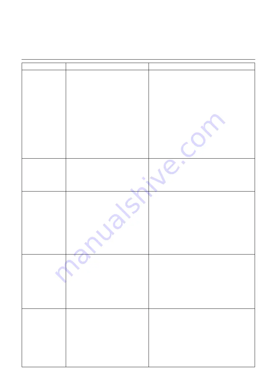
elco AEROTOP G Installation, Operation And Maintenance Manual Download Page 51

Problem 

Cause 

Remedy, Action 

225: Low pressure  
 

problem


Low pressure problem 
Affects contact E9 at the LOGON B WP61. 
Low pressure switch in the cooling circuit  
triggered. 

Insufficient flow of air through evaporator  

A1  Ice formation 
A2  Evaporator dirty 
A3  Grating dirty 
A4  Fan not running or not running enough 


Leak in cooling circuit 


Injection valve defective, frozen or clogged 

Incorrect amount of coolant 

Leak in cooling circuit 


A1  Check thawing function (check sensor) 
A2  Clean evaporator  
A3  Clean grating 
A4  Check speed, adjust, check voltage 
 
If everything in A can be excluded:  
 

Measure temperature difference between filter dryer input  


and output (

T max 3 K) 

Check, set or replace injection valve 

Empty and refill in accordance with type plate  

Oil residue in the unit is another indication of a leak in  


the cooling circuit. 

 
The refrigerant technician must be called in such cases.


226: Winding protection  
 

compressor


Affects contact E11 at the LOGON B WP61. 

Phase interruption (compressor gets hot) 


Phase reverse (incorrect rotary field) 

Phase loss 

Phase asymmetry 

Short circuit  


Check all three phases (wait until the winding protection  


has cooled, can take several hours). 

Check electrical connection. 

Check whether oil sump heater is working. 

Make sure the rotation is right. 

Eliminate short circuit 

247: Thawing problem


After the fourth thawing attempt, the evaporator  
sensor on the cooling circuit (B84) still has not  
reached the evaporator temperature  
(Para. 2954) set at the LOGON B WP61. 

Sensor B91 positioned incorrectly 

Sensor B84 defective/no longer in the  


required position 


Not enough energy for thawing 


(water temperature in heating circuit too 

low) 
 

Flow rate to the condenser too low


Position sensor properly, replace sensor if defective 

Check sensor position. Check function (measure actual  


temperature in all injection pipes and compare with  


B84 value) 


Switch on electric heating element until the minimum  


water temperature is reached. Close part of heating circuit. 


Check pumps for functions, check return and switch valves 


358: Soft starter


Actions in relation to the LOGON B WP61’s E25 
(EX5) contact.  
The soft starter signals an alarm via the auxiliary 
relay. The alarms envisaged may be:  
- Incorrect phases sequence 
- Line voltage off the scale  
- Frequency outside the range 
- Jammed rotor 
- Start-up ramp > 1 s  
- Over-temperature  
- Excess current (during the bypass) 
- Supply voltage imbalance  

Carry out the failure reset (HMI) and check the following:  
A  Check the sequence of the 3 input phases on the soft starter 
B  Measure the voltage of the 3 phases 
C  Check the electrical connections  
D  Check that the magnetic field is rotating clockwise  
    (check the sequence of the 3 phases in the compressor ter            
minal block)  
E  Measure the current absorption 
F  In the event of the load being lightened, integrate an addi-

tional relay;


  see the discharger info.  

12:  PWW charge temp.  
 

HP too low  

The controller stores the potable water tempera- 
ture at which the charging with the heat pump  
was last interrupted when the heat pump  
reached the high pressure, hot gas or maximum  
switch-off temperature limit. 
If the value is lower than the setting “PWH  
charge temp HP minimum" (control line 7092),  
the service symbol will appear in the display  
and details of the service in the info line. 

This parameter cannot be reset. If the minimum PWW charging  
temperature is exceeded again the next time potable water is  
charged, the service function will also be reversed. If it is still  
not reached, the service message will remain. 
1. 

Check placement of the of the B3 sensor 

2. 

Setpoint too high for PWW temp. 

3. 

Charging type activated with B3 and B31, switch to B3 

only 
4. 

Temperature transmission to PWW sensor 


poor, improve with spring clamp 

5. 

In the mother/child storage the PWW charge should  


occur at different levels via a three-way valve. 

6. 

Heat exchange area of the storage is too small 

Maintenance 


Troubleshooting 

51 

Summary of Contents for AEROTOP G

Page 1: ...Installation operation and maintenance manual AEROTOP G Air Water Heat Pump for installation outdoors 06 2015 Art No 420010405804...

Page 2: ...mp STRATOS PARA 25 1 9 23 INSTALLATION 24 Transportation General installation notes 24 Pedestal 25 Pipeline Condensate drain pipe 26 Checklist for correct set up 27 Delivery to installation site 28 Hy...

Page 3: ...ent through the reduction of emissions and the reduced use of primary ener gy In order for your new heating system to function efficiently please observe the following The heat pump system must be siz...

Page 4: ...installation connection and commissioning of the heat pump must be carried out by a specialised expert in compliance with national appliance regulations and with the instructions for use Any work on...

Page 5: ...p must be registered with the local power supply company Do not tilt the heat pump more than 15 when transporting Avoid exposing the heat pump to any type of moisture or hu midity Protect the heat pum...

Page 6: ...if taking into account the aforementioned condi tions After sizing the heat pump for nor mal operations it may not be possi ble to generate all heating neces sary Please comply also with the followin...

Page 7: ...with copper pipes with aluminium fins The fins have a hydrophilic cov er for better down flow of con densation and optimised de frosting Cooling circuit Hermetically sealed loaded at the factory and t...

Page 8: ...cket 2 1 switch panel 3 1 control unit to the controller 4 1 outdoor sensor 5 4 vibration absorbent adjustable feet 6 4 hose seals 7 1 set of documentation 8 2 vibration absorbent hoses 9 4 transport...

Page 9: ...4 40 5 7 COP 2 10 2 10 2 20 1 9 Evaporator air side Evaporator Grooved copper pipes and fins in hydrophilic aluminium Fan Axial Air flow min max m h 3500 4000 4600 2800 5200 Available static pressure...

Page 10: ...C16A 3 polig C20A 3 polig C25A 3 polig C25A 3 polig Control voltage supply 230V 50Hz Power input data Heat pump max power input without heating element PHP kW 3 17 5 28 6 16 8 20 Heating element power...

Page 11: ...WP 61 Connections Water inlet DN25 IG 1 DN25 IG 1 DN25 IG 1 DN25 IG 1 Heating water outlet DN25 IG 1 DN25 IG 1 DN25 IG 1 DN25 IG 1 Condensation discharge DN25 IG 1 DN25 IG 1 DN25 IG 1 DN25 IG 1 Power...

Page 12: ...rator Grooved copper pipes and fins in hydrophilic aluminium Fan axial Air flow min max m h 3500 4000 Available static pressure without ducts Pa 47 45 Min external air temperature in heating C 18 Max...

Page 13: ...ement 4 kW C40A 1 polig C50A 1 polig External fuse heating element 6 kW A C50A 1 polig C63A 1 polig Control voltage supply 230V 50Hz Power input data Heat pump max power input without heating element...

Page 14: ...61 Connections Water inlet DN25 IG 1 DN25 IG 1 Heating water outlet DN25 IG 1 DN25 IG 1 Condensation discharge DN25 IG 1 DN25 IG 1 Power supply 1 x 35mm 1 x 35mm Sound power level Lwa 3 nominal power...

Page 15: ...7 10 15 20 Outlet water temperature C 35 Heating capacity kW 4 41 4 98 5 28 6 36 8 64 9 73 11 91 14 03 Power consumption kW 1 64 1 67 1 70 1 72 1 86 1 89 2 00 2 10 COP 2 69 2 98 3 10 3 69 4 66 5 16 5...

Page 16: ...erature C 35 Heating capacity kW 6 39 7 22 7 65 9 22 12 52 14 10 17 27 20 34 Power consumption kW 2 37 2 42 2 47 2 50 2 69 2 73 2 90 3 05 COP 2 69 2 98 3 10 3 69 4 65 5 16 5 96 6 68 Outlet water tempe...

Page 17: ...99 9 36 10 32 11 80 14 10 17 40 20 19 23 14 Power consumption kW 2 94 3 01 3 09 3 24 3 33 3 39 3 52 3 66 COP 2 72 3 11 3 35 3 64 4 23 5 13 5 74 6 32 Outlet water temperature C 45 Heating capacity kW...

Page 18: ...2 96 3 76 4 09 4 7 4 89 Outlet water temperature C 55 Heating capacity kW 11 96 10 76 7 65 9 55 10 40 11 98 12 60 Power consumption kW 7 06 5 75 3 33 3 28 3 30 3 35 3 36 COP 1 69 1 87 2 30 2 91 3 15...

Page 19: ...18 96 21 69 24 39 Power consumption kW 5 79 5 87 5 92 6 20 6 26 6 11 6 18 6 22 COP 1 84 2 00 2 15 2 38 2 68 3 10 3 51 3 92 Outlet water temperature C 55 Heating capacity kW 11 96 12 79 14 46 16 18 18...

Page 20: ...ot allow these values to fall below this threshold Pipelines should be kept as short as possible and be laid in such a way that pressure loss and heat loss are kept to a minimum Poorly or improp erly...

Page 21: ...4 Fin evaporator CU Aluminium 5 Controls 6 Circulating pump G07 X 7 Electric heating element 2 4 6 KW 8 Condenser heat exchanger ALFA LAVAL 9 Vibration absorbent rubber buffers Diameter 70 mm Height...

Page 22: ...Technical Data Delivery pressure circulating pump Aerotop G07 X G10 X G07 14M YONOS PARA RS 25 7 5 180 Pumping medium water Media temperature 35 C Density 1000 kg m3 22...

Page 23: ...Technical Data Delivery pressure circulating pump Aerotop G12 STRATOS PARA 25 1 9 180 Pumping medium water Media temperature 35 C Density 1000 kg m3 23...

Page 24: ...ifted and transported using only the designated transport aids 4 L sections at the bottom of the unit The AEROTOP G should be set up on level ground and aligned Installation The safety regulations and...

Page 25: ...wn in figu res The layer thicknesses are average values and have to be adapted to local conditions The rules of construction enginee ring must be observed For pipes that must be included under the hea...

Page 26: ...harged from the collection tank by means of a tube In the design and installation of the condensate drain you should consider the following points It is necessary to set up the condensate discharge pi...

Page 27: ...air noise Construction measures can reduce noise plants cannot Use constructional measures to interrupt the spreading of noise from the heat pump direct noise propagation Use solid walls fences palis...

Page 28: ...Installation Delivery to installation site 2 3 1 n 17 4x 8x M10 4x 4x 28...

Page 29: ...Installation Delivery to installation site 29...

Page 30: ...line system of new as well as retrofitted systems must be thoroughly flushed Residue left in the heater pipes will damage the heat exchangers and cause the heat pumps to malfunction It is recommended...

Page 31: ...Installation Hydraulic connections assembly instructions 3 1 n 3 1 4 2x n 46 1 x 2 1 4 10 x 31...

Page 32: ...Installation Hydraulic connections assembly instructions 4 7 5 8 4x 1 4 6 2 x 32...

Page 33: ...thermostatic valves requires approval by the system manager In this case calculate loss of head to determine the wa ter flow For an approximate calculation of the system s minimum volume consider a v...

Page 34: ...of heat e g chim neys sun flues heating bod ies air currents The power connection of the heat pump must be carried out by qualified personnel and in compliance with national appli ance regulations In...

Page 35: ...Installation Instruction for the installation of control unit The control unit must be installed indoors temperature range 5 C to 40 C 2 3 1 4x 4x 164 270 2x 35...

Page 36: ...Installation Instruction for the installation of control unit black wire CL 5 4 36...

Page 37: ...oller LOGON B WP61 4 Mains supply plug Mains connector phase AC 230 V Main connector neutral connector 5 Contactor electric heating element 6 Circuit breaker 3x400V N 7 Circuit breaker 230V 8 Soft sta...

Page 38: ...supply plug Mains connector phase AC 230 V Main connector neutral connector 5 Contactor electric heating element 6 Circuit breaker 230V 7 Soft starter and 3 phase relay 8 Thermostat electric heating e...

Page 39: ...pump controller LOGON B WP61 4 Mains supply plug Mains connector phase AC 230 V Main connector neutral connector 5 Contactor electric heating element AEROTOP G M 6 Circuit breaker 3x400V N 7 Circuit b...

Page 40: ...92 M19 Fan z UX1 M1 Compressor Q K1 N2 Control unit b G CL CL N1 Controller LOGON B WP61 Condenser pump AEROTOP G X Other important components that have to be wired in the system Description RVS61 plu...

Page 41: ...regulation temperature sensor y BX5 Condenser pump Descrizione P3 controller connector EEV controller output PB6 Evaporator pressure monitoring J2 J3 GMD 5V B6 PB3 Evaporator temperature sensor J3 B3...

Page 42: ...ion To carry out the commissioning the following people must be in attend ance Designer provides the operat ing parameters Installer in charge of function ality and regulating the heating system Syste...

Page 43: ...ce of substances and ad ditives in the heating water can jeop ardise the correct operation and life duration of the heat pump Therefore before replacing the old sys tem heat up the whole system and em...

Page 44: ...le entry points Terminals Check connections tight Check soft starter amperes and DIP switch set correctly Check rotating field and protective ground conductor Fuses Correct strength Is there energy pr...

Page 45: ...e bubbles visible Check for any noise compressor running smoothly Check for structure borne noise transmission flexible connection sound absorbing pipe suspension vibration transmission over the floor...

Page 46: ...0 421 10 0 4 574 20 0 1 218 50 0 407 9 0 4 358 21 0 1 170 8 0 4 152 22 0 1 125 7 0 3 958 23 0 1 081 6 0 3 774 24 0 1 040 5 0 3 600 25 0 1 000 4 0 3 435 26 0 962 3 0 3 279 27 0 926 2 0 3 131 28 0 892 1...

Page 47: ...34 0 136 60 20 0 12 09 74 0 1 98 33 0 129 70 21 0 11 63 75 0 1 92 32 0 123 20 22 0 11 20 76 0 1 87 31 0 117 10 23 0 10 78 77 0 1 81 30 0 111 30 24 0 10 38 78 0 1 76 29 0 105 70 25 0 10 00 79 0 1 71 2...

Page 48: ...99 0 0 99 8 0 38 76 46 0 4 74 100 0 0 97 7 0 37 05 47 0 4 59 101 0 0 94 6 0 35 43 48 0 4 44 102 0 0 92 5 0 33 89 49 0 4 30 103 0 0 90 4 0 32 43 50 0 4 16 104 0 0 87 3 0 31 04 51 0 4 02 105 0 0 85 2 0...

Page 49: ...carried out only by specifically trained technicians Any work carried out on the heat pump by unauthorised persons or companies will result in the loss of any right to warranty Cleaning the condensat...

Page 50: ...s don t close A3 Heating or potable water circulation pump not running A4 Overflow valve missing or set incorrectly A5 Heating curve set too steep The module switches the particular unit to the safety...

Page 51: ...njection pipes and compare with B84 value C Switch on electric heating element until the minimum water temperature is reached Close part of heating circuit D Check pumps for functions check return and...

Page 52: ...Electric heating element should be configured in the program ming menu Heat pump disabled Info about Parameter 8006 status HP 1 Disabled outdoor temperature 2 Disabled external External disablement o...

Page 53: ...1 152 103 151 110 154 99 155 Warmer climate condition s 172 214 171 213 161 204 154 214 Annual energy consumption Average climate condition QHE 2617 2870 3866 3623 4972 5626 6742 5266 Colder climate c...

Page 54: ...bivalent temperature Pdh kW 5 0 7 2 9 9 11 1 Tj operation limit temperature Pdh kW 4 2 6 1 7 8 10 3 For air to water heat pumps T j 15 C if TOL 20 C Pdh kW Bivalent temperature Tbiv C 8 8 8 10 Cyclin...

Page 55: ...to water heat pumps Operation limit tempe TOL C 18 20 Cycling interval efficiency COPcyc 2 55 2 21 Heating water operating limit temperature WTOL C 53 55 Supplementary heater Rated heat output Psup k...

Page 56: ...Elecromagnetic Compatibility Directive 2010 30 EC Directive on the indication by labelling and standard product information of the consumption of energy and other resources by energy related products...

Page 57: ...Notes 57...

Page 58: ...Service www elco net...

Reviews: