


VIA!2-8.4 USER’S GUIDE
©
ELAN Home Systems 2006 • All rights reserved. 1-5
Operation
The VIA!2-8.4 Wireless Touch Panel is simple and intuitive to operate.
Each source can be custom programmed to work just the way the user
desires.
ELAN recommends using the provided stylus to operate the touch screen.
Avoid touching with your fingers, as oil from your fingertips can be difficult
to remove. The stylus for the VIA!2's touch screen is located in the upper
right corner of the panel.
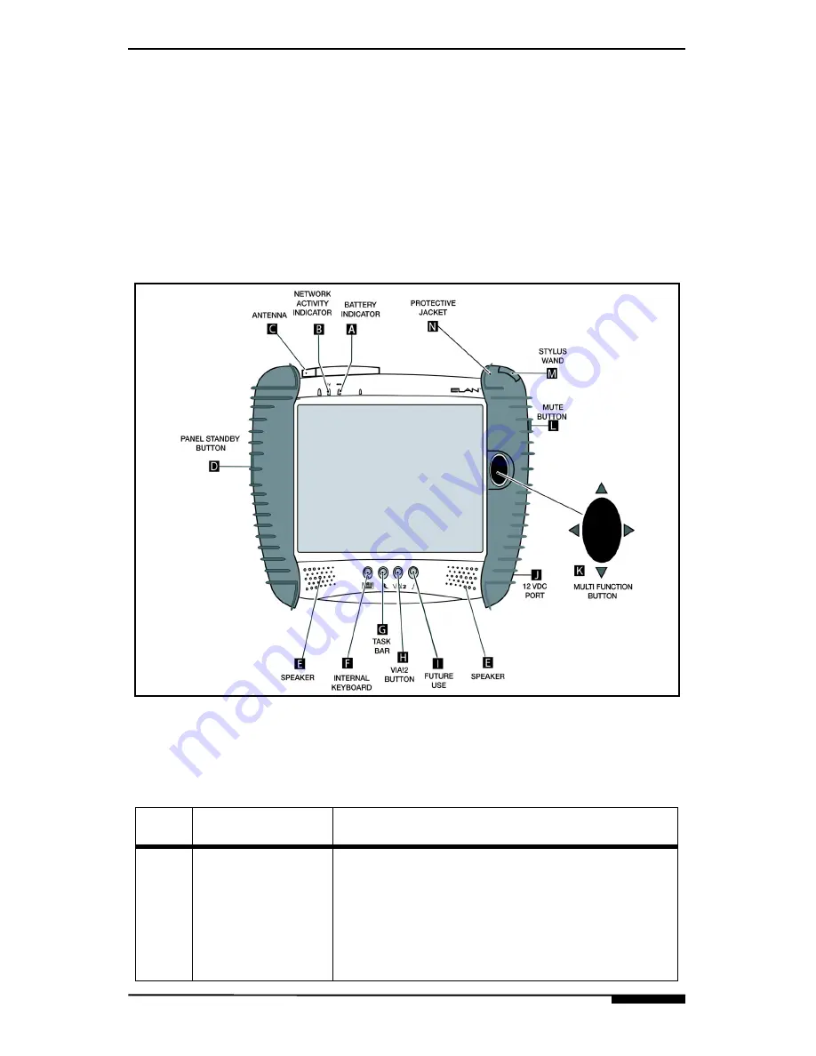
Panel Buttons & Features
Figure 1-2: VIA!2-8.4 Wireless Touch Panel Buttons & Features
Table 1-3: Front Panel Buttons & Features
Item
Item
Description
A
Battery
Indicator
Indicates power is on and VIA!2-8.4 is active.
Also indicates unit is docked in the desktop cra-
dle. A solid blue LED means panel is fully
charged, a blue LED flashing means battery is
charging. A solid amber LED means battery is
low, a flashing amber LED indicates battery
power critically low and the panel is preparing to
go in to turn off.
Summary of Contents for ViA 2-8.4
Page 1: ...Revision A...
Page 2: ......
Page 24: ...USER S GUIDE VIA 2 8 4 1 14 ELAN Home Systems 2006 All rights reserved...
Page 34: ...The ELAN Network VIA VALET6 4 3 2 ELAN Home Systems 2005 All rights reserved...
Page 35: ......


