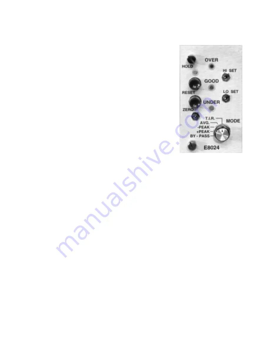
E8024 - PEAK DETECTOR, TIR MODULE WITH LIMIT LIGHTS
3-6 Functional Description
The E8024 peak detector, average, TIR module, accepts a lower bay
signal source and stores its value as a peak or TIR in analog memory.
The contents of this memory are then displayed on the bargraph
readout.
In addition, the E8024 module has “Good”, “Under”, and “Over” limit
lights, which detect signals that have exceeded the calibrated set point.
This module is installed in the upper bay and will operate with any
lower bay module.
The E8024 is used on applications which require a measurement of a
dynamic signal such as concentricity, out of round, etc., and is usually
read as a total indicator reading (TIR). A TIR signal on a basic
Trendsetter™ column will cause the bargraph to move up and down,
requiring the operator to note the highest and lowest readings and
calculate their difference to determine if the part is within tolerance.
With the E8024 TIR module, the column bargraph will rise from the
preset bottom starting point and will remain at its highest reading,
showing the total reading. As this total reading is displayed, the limit
lights can also be utilized to facilitate the decision making process for
the operator.
Along with the ability to display the total reading of a runout, the E8024 can be used to display either a
“+” or “-” peak signal. This feature is equally useful as TIR and is typically used as follows:
In matching an I.D. and an O.D., out of round is always present to some extent. The E8024 module
will take into account the mininum bore size and maximum shaft size caused by any out of round
condition and will enable the correct clearance to be computed for the maximum material condi-
tion. The roundness reading will, of course, depend on the gage geometry and may require a three
point O.D. check to eliminate the effects of three point lobing, etc.
In a typical setup, the I.D. and O.D. would be gaged in two fixtures, either air or electronic contact,
and the values displayed on two columns operating in the “Peak” mode. Each part would be rotated
once in the fixture. The I.D. column would latch on the minimum (“-” peak) reading, the O.D. column
would latch on the maximum (“+” peak) reading. These two signals can now be compared in a third
Trendsetter™ column equipped with a Sum & Difference module (E8026) and the actual clearance at
maximum material condition can be displayed. This system will completely eliminate operator deci-
sion making in determining the actual maximum and minimum readings.
Controls
Mode Switch
Through the mode selector switch one of five operating modes may be selected. They are as
follows:
1. Bypass — This mode allows input signals to pass from the various signal conditioners to
the bargraph readout without any interaction from the E8024 module. This mode is used
25


