background image

- 10 

-

IT

ALIANO

INSTALLAZIONE

NOTE GENERALI

Gli allacciamenti scarico fumi e idraulico deve essere ese-

guiti da personale qualificato che possa rilasciare docu

-

mentazione di conformità di installazione secondo le norme 

nazionali.  

In Italia è necessario fare riferimento alla norma dichiarazione 

di conformità ai sensi del D.M. 37/2008 (ex L. 46/90) e secon

-

do le norme UNI 10683 e UNI 10412-2/2009. 

In caso di installazione in condominio, chiedere parere preven-

tivo all’amministratore.

VERIFICA DI COMPATIBILITA’ CON ALTRI DISPOSITIVI

In Italia la termostufa NON deve essere installata nello stesso 

ambiente in cui si trovano apparecchi da riscaldamento a gas 

del tipo B (es. caldaie a gas, stufe e apparecchi asserviti da 

cappa aspirante - rif. UNI 10683 e 7129). 

In generale la termostufa potrebbe mettere in depressione 

l’ambiente compromettendo il funzionamento di tali apparecchi 

oppure esserne influenzata.

VERIFICA ALLACCIAMENTO ELETTRICO (posiziona-

re la presa di corrente in un punto facilmente accessibile)

La termostufa è fornita di un cavo di alimentazione elettrica 

da collegarsi ad una presa di 230V 50 Hz, preferibilmente con 

interruttore magnetotermico. 

L’impianto elettrico deve essere a norma; verificare in partico

-

lare l’efficienza del circuito di terra. 

La linea di alimentazione deve essere di sezione adeguata alla 

potenza della termostufa.

La non efficienza del circuito di terra provoca mal funziona

-

mento di cui Edilkamin non si potrà far carico. 

In caso di problemi alla rete elettrica consultare un elettricista 

per valutare l’installazione di un gruppo di continuità di almeno 

800 Va a onde sinusoidali. 

Variazione maggiori del 10% di alimentazione possono provo-

care problemi al prodotto.

PRESA D’ARIA (da realizzare inderogabilmente)

É indispensabile che il locale dove la termostufa è collocata 

abbia una presa di aria di sezione di almeno 80 cm² tale da 

garantire il ripristino dell’aria consumata per la combustione. 

In alternativa, è possibile prelevare l’aria per la termostufa di-

rettamente dall’esterno attraverso un prolungamento in acciaio 

del tubo di ø 4 cm ubicato sullo schienale della termostufa 

stessa. 

Il tubo deve essere di lunghezza inferiore a 1 metro e non deve 

presentare curve. 

Deve terminare con un tratto a 90° gradi verso il basso o con 

una protezione antivento. 

In ogni caso lungo tutto il percorso del condotto presa aria deve 

essere garantita una sezione libera di almeno 12 cm². 

Il terminale esterno del condotto presa aria deve essere protetto 

con una rete anti insetti che comunque non riduca la sezione 

passante utile di 12 cm².

POSIZIONAMENTO E DISTANZE DI SICUREZZA PER 

ANTINCENDIO

Per il corretto funzionamento, la termostufa deve essere posi-

zionata in bolla. 

Verificare la capacità portante del pavimento.

La termostufa deve essere installata nel rispetto delle seguenti 

condizioni di sicurezza:

- distanza minima sui lati e sul retro di 10 cm dai materiali 

infiammabili. 

- davanti alla termostufa non possono essere collocati materiali 

infiammabili a meno di 80 cm. 

- se la termostufa è installata su un pavimento infiammabile 

deve essere interposta una lastra di materiale isolante al calore 

che sporga almeno 20 cm sui lati e 40 cm sul fronte.

Se non risultasse possibile prevedere le distanze sopra indicate,

è necessario mettere in atto provvedimenti tecnici ed edili per

evitare ogni rischio di incendio. 

In caso di contatto con parete in legno o altro materiale infam-

mabile, è necessario coibentare il tubo di scarico fumi con fibra 

ceramica o altro materiale di pari caratteristiche. 

Summary of Contents for DAISY

Page 1: ...on brug og vedligeholdelse pag 158 PT Instalação uso e manutenção pag 184 PL Instalacja obsługa i konserwacja pag 226 CZ Návod na použití a instalaci str 236 DAISY Termostufa ventilata a pellet Ventilated pellet stove Thermopoêle ventilé à granulés Termoestufa ventilada de pellet Belüfteter wassergeführter Pellets Heizofen Geventileerde pelletthermokachel Ventileret pilleovn Salamandra a água pell...

Page 2: ...mmerciale EDILKAMIN denominata DAISY N di SERIE Rif Targhetta dati Dichiarazione di presta zione DoP EK 105 a pag 10 Rif Targhetta dati Altresì dichiara che termostufa a pellet di legno DAISY rispetta i requisiti delle direttive europee 2014 35 UE Direttiva Bassa Tensione 2014 30 UE Direttiva Compatibilità Elettromagnetica EDILKAMIN S p a declina ogni responsabilità di malfunziona mento dell appar...

Page 3: ...tto e garanzia Il prodotto è identificato in modo univoco da un numero il tagliando di controllo che trovate sul certificato di garanzia Le chiediamo di conservare il certificato di garanzia che ha trovato nel prodotto il documento fiscale di acquisto che le ha rilasciato il rivenditore la dichiarazione di conformità che la ha rilasciato l installatore Le condizioni di garanzia sono riportate nel ...

Page 4: ... norma UNI 8065 1989 Trattamento dell acqua negli impianti termici ad uso civile IN CASO DI FALLITAACCENSIONE NON RIPETE RE L ACCENSIONE PRIMA DI AVERE SVUOTATO IL CROGIOLO LA TERMOSTUFA NON DEVE MAI FUNZIONARE SEN ZAACQUA NELL IMPIANTO UNA EVENTUALE ACCENSIONE A SECCO COMPRO METTEREBBE LA TERMOSTUFA LA TERMOSTUFA DEVE FUNZIONARE CON PRESSIO NE DI UN 1 5 BAR CIRCA L apparecchio non è destinato a e...

Page 5: ...ufa Le ceneri cadono sotto e a fianco del crogiolo dove è alloggiato un cassetto cenere da cui periodicamente devono essere rimos se aiutandosi con aspirapolvere a freddo L acqua calda prodotta dalla termostufa viene inviata trami te circolatore incorporato nella termostufa stessa al circuito dell impianto di riscaldamento La termostufa è progettata per funzionamento con vaso di espansione chiuso ...

Page 6: ...bustione che consente un funzionamento ottimale in qualunque condizione grazie a due sensori che rilevano il livello di pressione nella camera di combustione e la temperatura dei fumi La rilevazione e la conseguente ottimizzazione dei due parametri avviene in continuo in modo da correggere in tempo reale eventuali anomalie di funzionamento Il sistema ottiene una combustione costante regolando auto...

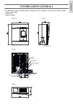
Page 7: ...ta fumi ritorno 3 4 carico scarico mandata 3 4 valvola sicurezza 3 bar Ø 8 cm uscita fumi Ø 4 cm aria combustione 100 43 11 5 38 5 34 5 41 4 5 14 5 11 19 15 5 18 21 5 FRONTE ritorno 3 4 carico scarico mandata 3 4 valvola sicurezza 3 bar Ø 8 cm uscita fumi Ø 4 cm aria combustione 100 43 11 5 38 5 34 5 41 4 5 14 5 11 19 15 5 18 21 5 LA TERMOSTUFA DAISY È DISPONIBILE CON FRONTALE IN CERAMICA IN TRE V...

Page 8: ...vviso e a suo insindacabile giudizio INFORMAZIONI GENERALI Il volume riscaldabile è calcolato considerando un isolamento della casa come da L 10 91 e successive modifiche e una richiesta di calore di 33 Kcal m ora E importante tenere in considerazione anche la collocazione della termostufa nell ambiente da scaldare DATI TECNICI PER DIMENSIONAMENTO CANNA FUMARIA che deve comunque rispettare le indi...

Page 9: ...lta viene lanciata una fase di blocco Termostato di sicurezza sovratemperatura acqua Legge la temperatura dell acqua nella termostufa In caso di temperatura troppo alta interrompe l alimentazione elettrica al motoriduttore Nel caso che il termostato sia intervenuto deve essere riarmato intervenendo sul pulsante di emergenza rosso posizionato sul lato sinistro della termostufa A fig 1 Valvola di so...

Page 10: ...ossono provo care problemi al prodotto PRESA D ARIA da realizzare inderogabilmente É indispensabile che il locale dove la termostufa è collocata abbia una presa di aria di sezione di almeno 80 cm tale da garantire il ripristino dell aria consumata per la combustione In alternativa è possibile prelevare l aria per la termostufa di rettamente dall esterno attraverso un prolungamento in acciaio del t...

Page 11: ... 3 E necessario se lo scarico non si inserisce in una canna fumaria esistente un tratto verticale e un terminale antivento riferimento UNI 10683 Il condotto verticale può essere interno o esterno dell edificio Se il canale da fumo tratto di tubo che va dalla termostufa alla canna fumaria si inserisce in una canna fumaria esistente questa deve essere autorizzata per combustibili solidi Se la canna ...

Page 12: ...te V poste sul retro della termostufa Smontare la staffa metallica D di fissaggio dell elemento orizzontale inferiore in ceramica D vedi pagina 17 fig 5 Fig 4 5 Asportare il gomito N in dotazione dal bocchettone della chiocciola fumi Montare il tubo uscita orizzontale P optional tramite fa scetta in dotazione sul bocchettone della chiocciola fumi Fig 6 Rimontare la ceramica inferiore e i due fianc...

Page 13: ...iale impiegato nel circuito deve essere adatto ad sop portare eventuali sovratemperature Lo scarico della valvola di sicurezza deve essere raggiungibi le e visibile L acqua di scarico deve essere convogliata in un tubo verticale attraverso un imbuto con prese d aria antiriflus so opportunamente distanziato dal punto di scarico Il tubo di convogliamento deve avere le seguenti caratteristi che Non d...

Page 14: ...ro GR Riduttore di pressione MI Mandata Impianto P Pompa circolatore RA Radiatori RI Ritorno Impianto S Scarico SB Scaldabagno ST Sonda Temperatura TC Termostufa V Valvola a sfera VA Valvola automatica scarico aria Vec Vaso espansione chiuso VSP Valvola di sicurezza VST Valvola di scarico termico N B I presenti schemi sono indicativi la corretta esecuzione è a cura dell idraulico ALLACCIAMENTI IDR...

Page 15: ...te n 1 elemento orizzontale superiore in ceramica F fig 3 n 1 elemento orizzontale inferiore in ceramica G fig 7 n 12 perni zigrinati M4 n 24 rondelle Per il montaggio procedere come segue Fig 2 Aprire il coperchio pellet e allentare la vite X al suo interno Fig 3 Rimuovere il top E completo del coperchio carico pellet e la griglia aria Sfilare i due fianchi metallici M allentando le due viti zigr...

Page 16: ...erto filettato sull elemento orizzontale in ceramica La staffa metallica deve essere centrata sull elemento orizzonta le in ceramica Utilizzare per ciascuna posizione di fissaggio la seguente minu teria n 1 vite M4 a testa zigrinata n 1 rondella Ø5x15 interposta tra gli elementi orizzontali in ceramica e le staffe metalliche n 1 rondella Ø5x15 interposta tra la staffa metallica e la vite M4 a test...

Page 17: ...tallici M e il top E precedente mente smontati dalla termostufa Fig 8 La figura rappresenta la termostufa completamente allestita Fig 9 Fissare la stufa a muro mediante le squadrette S e le staffe R fornite in dotazione oppure utilizzare sistemi alternativi che garantiscano la sua stabilità MONTAGGIO RIVESTIMENTO fig 8 fig 7 fig 9 S R F G C D E M ...

Page 18: ... tarare la termostufa in base al tipo di pellet e alle condizioni di instal lazione es caratteristiche della canna fumaria La messa in servizio da parte del CAT è indispensabile per l attivazione della garanzia Il CAT dovrà anche Verificare che l impianto idraulico sia correttamente eseguito e sia dotato di vaso di espansione sufficiente a garantirne la sicurezza La presenza del vaso incorporato n...

Page 19: ...ione Sul display si visualizzano altre informazioni utili oltre alle icone descritte sopra Posizione Stand by si visualizza la temperatura mandata TM la temperatura impostata SET i Kg di pellet rimasti 15Kg nel serbatoio e l ora corrente In fase accensione AVVIO in aggiunta alle informazioni visualizzate in stand by Fase di lavoro si visualizza la temperatura mandata TM la temperatura impostata SE...

Page 20: ... tronica Premendo successivamente il tasto M appaiono in sequenza e possono essere regolati i seguenti dati Giorno Mese Anno Ora Minuti Giorno della settimana La scritta SALVO DATI da confermare con M permette di verificare l esattezza delle operazioni compiute prima di confermarle viene allora visualizzato sul display la scritta Salvataggio Le operazioni di accensione spegnimento cambio temperatu...

Page 21: ... attivare il sistema è necessario caricare nel serbatoio un sacchetto di pellet e utilizzare la stufa fino ad esaurimen to del combustibile caricato Ciò al fine di ottenere un breve rodaggio del sistema Dopo di che è possibile riempire completamente il serbatoio e quindi mettere in funzione la termostufa Durante il funzionamento nel momento in cui sarà possibile caricare un intero sacchetto da 15 ...

Page 22: ...to cenere Scrostare il crogiolo con la spatolina in dotazione pulire even tuali occlusioni delle asole IN NESSUN CASO SCARICARE I RESIDUI NEL SER BATOIO DEL PELLET Estrarre e svuotare il cassetto cenere 2 fig A in un contenito re non infiammabile la cenere potrebbe contenere parti ancora calde e o braci Aspirare l interno del focolare il piano fuoco il vano attorno al crogiolo dove cade la cenere ...

Page 23: ... al prodotto e esonare Edilkamin da ogni responsabilità su eventuali danni da ciò derivanti E vietata ogni modifica non autorizzata SMALTIMENTO Alla fine della vita utile smaltire il prodotto secondo le normative vigenti Ai sensi dell art 26 del Decreto Legislativo 14 marzo 2014 n 49 Attuazione della direttiva 2012 19 UE sui rifiuti di apparecchiature elettriche ed elettroniche RAEE Il simbolo del...

Page 24: ...ione del tubo di scarico dei fumi o della canna fumaria verificare da un tecnico abilitato spazzacamino Intervento del termostato di sicurezza del serbatoio Verificare che attorno alla stufa non vi siano oggetti che ostruiscano la ventilazione oppure i ventilatori siano guasti o fermi in tal caso chiamare CAT 4 Segnalazione BloccoAF NO Avvio interviene se in un tempo massimo di 15 minuti non compa...

Page 25: ...on display spento standby premere e mantenere premuto il tasto 0 I per 10 Trascorsi i 10 compare a display il messaggio RICERCA RETE rilasciare quindi il tasto 0 I significa che la fase di ricerca automatica si è attivata In qualche secondo avverrà la sincronizzazione automatica del canale radio 14 Inconveniente Durante la fase di accensione salta il differenziale Azioni Verificare le condizioni d...

Page 26: ... 6 Posso scaricare i fumi delle termostufa direttamente a parete NO lo scarico a regola d arte UNI 10683 deve raggiungere il colmo del tetto e comunque per il buon funzionamento è neces sario un tratto verticale di almeno 1 5 metri ciò ad evitare che in caso di black out elettrico o di vento si formi seppur modesta quantità di fumo nel locale di installazione 7 E necessaria una presa di aria nel l...

Page 27: ...e da fumo la canna fumaria riceve solo lo scarico della termostufa Il canale da fumo tratto di condotto che collega la termostufa alla canna fumaria presenta massimo 3 curve massimo 2 metri in orizzontale il comignolo oltre la zona di reflusso i tubi di scarico sono in materiale idoneo consigliato acciaio inox nell attraversamento di eventuali materiali infiammabili es legno sono state prese tutte...

Page 28: ...led DAISY Year of manufacture Ref Data nameplate Declaration of performance DoP EK 105 see page 39 Ref data tag plate In addition it is hereby declared that The wood pellet Boiler stoves DAISY is in compliance with the requirements of the European directives 2014 35 UE Low voltage directive 2014 30 UE Electromagnetic compatibility directive EDILKAMIN S p a will decline all responsability of malfun...

Page 29: ...ning testing This must be carried out by an EDILKAMIN authorised Technical Assistance Centre TAC to guarantee proper operation Commissioning as specified in standard UNI 10683 consists in a series inspections to be performed with the boiler stove installed in order to ascertain the correct operation of the system and its compliance to applicable regulations Incorrect installation incorrect mainten...

Page 30: ...Systems For Civil Use SHOULD IGNITION FAIL DO NOT RE IGNITE UNTIL YOU HAVE EMPTIED THE COMBUSTION CHAMBER THE BOILER STOVE MUST NEVER BE MADE TO OPE RATE WITHOUT WATER IN THE SYSTEM IT CAN BE DAMAGED IF IT IS IGNITED WITH NO WA TER IN THE SYSTEM MUST BE MADE WITH A PRESSURE OF ABOUT 1 5 BAR The appliance is not designed to be used by people including children with reduced physical sensorial or men...

Page 31: ... of the stove The ash falls under and beside the crucible in which is housed an ash tray from which the ash must be periodically removed by vacuuming when cool The hot water produced by the boiler stove is transferred via a circulator built into the boiler stove itself to the heating system circuit The boiler stove is designed to function with closed expansion tank and pressure valve both of which...

Page 32: ...in the combu stion chamber and smoke temperature The detection of and subsequent optimisation of these two parameters is continuous in order to correct operation anomalies in real time The LEONARDO system offers constant combustion automatically regulating the draft based on the characteristics of the chimney flue bends length shape diameter etc and environmental conditions wind humidity atmospher...

Page 33: ...ar Ø 8 cm uscita fumi Ø 4 cm aria combustione 100 43 11 5 38 5 34 5 41 4 5 14 5 11 19 15 5 18 21 5 ritorno 3 4 carico scarico mandata 3 4 valvola sicurezza 3 bar Ø 8 cm uscita fumi Ø 4 cm aria combustione 100 43 11 5 38 5 34 5 41 4 5 14 5 11 19 15 5 18 21 5 GENERAL INFORMATION THE DAISY IS AVAILABLE WITH CERAMIC FRONT IN THREE DIFFERENT COLOURS cream ceramic black ceramic burgundy ceramic BACK SID...

Page 34: ...ting pressure of the water 1 5 bar Maximum operating temperature of the water 90 C Autonomy 6 19 hours Heatable volume 575 m3 Smoke outlet pipe diameter male 80 mm Air intake pipe diameter male 40 mm Weight including packaging 308 kg N B 1 keep in mind that external devices can cause interference to the operation of the circuit board 2 warning activity on live components maintenance and or checks ...

Page 35: ... for pump management and boiler power modulation If the temperature is too high it starts a shutdown Water overheating safety thermostat detects the water temperature in the thermo stoves If this is too high it triggers the shutdown process by disconnecting the electrical supply to the gear motor If the thermostat has trigge red a reaction it must be reset by means of the red emergency button at t...

Page 36: ...andatorily implemented The room where the boiler stove is located must have an air in take with cross section of at least 80cm2 to ensurereplenishment of the air consumed by combustion Alternatively the boiler stove air may be taken directly from outside through a 4 cm steel extension of the pipe In this case there may be condensation problems and it is necessary to protect the air intake with a g...

Page 37: ...oiler stove to the chimney flue is outside it must be appropriately insulated If the smoke channel is fitted inside a chimney flue the latter must be suitable for solid fuel If it is wider than 150 mm in diameter it must be improved by entering a pipe that has a suitable cross section and is made of suitable material e g 80 mm diameter steel All sections of the smoke duct must be accessible for in...

Page 38: ...the two milled screws V on the rear of the stove Remove the metal bracket D that fastens the lower horizon tal ceramic element D see page 45 Fig 5 Fig 4 5 Remove the elbow joint N provided from smoke extractor unit vent Install the horizontal output pipe P optional with the band provided on the smoke extractor unit vent Fig 6 Replace the lower ceramic element and two metal sides M remove the closi...

Page 39: ...stallation of a heating plant for example in Italy the referen ce is the Circular from ISPESL now INAIL of April 2011 This separation is easily carried out using KIT A2 from Edilka min The presence of a puffer inertial storage tank is recom mended but not mandatory Its presence has the advantage of freeing the stove from sudden demands from the heating system and allowing the integration of other ...

Page 40: ...le exchanger valves etc For information please contact your local dealer LEGEND ACS Household hot water AL Water supply input B Boiler C Fill Top up EV2 2 way electro valve EV3 3 way electro valve NA Normally Open NC Normally Closed GR Pressure reducer MI System in P Pump circulation RA Radiator RI System return S Drain TC Boiler stove V Spherical valve Vec Closed surge tank VSP Safety valve LEGEN...

Page 41: ...e packaged separately 1 upper horizontal ceramic element F Fig 3 1 lower horizontal ceramic element G Fig 7 12 milled pins M4 24 washers To fit proceed as follows Fig 2 Open the pellet cover and loosen the screw X inside Fig 3 Remove the top E complete with the pellet loading cover and the air grill Slide off the two metal sides M by loosening the two milled screws V on the rear of the stove C D f...

Page 42: ... the following hardware for each fixing position 1 x M4 milled screw 1 Ø5x15 washer placed between the horizontal ceramic ele ments and the metal brackets 1 Ø5x15 washer placed between the metal bracket and the M4 milled screw F G C D fig 6 fig 4 fig 5 C D Y Y Z CERAMICA SUPERIORE CO N S U P P O R T O M E T A L L I C O X posizione 4 posizione 2 posizione 5 posizione 3 posizione 2 posizione 3 posiz...

Page 43: ...Replace the metal sides M and the top E previously removed from the stove Fig 8 The figure shows the stove completely assembled Fig 9 Fix the stove to the wall using the square pieces S and bra ckets R provided or use alternative systems that ensure its stability COVERING INSTALLATION fig 8 fig 7 F G C D E M fig 9 S R ...

Page 44: ... glove supplied when filling the stove whilst it is running and therefore is hot Attention The first time the stove is lit the air water bleeding operation must be carried out by means of the small manual valve V Fig 2 positioned below the top grill The operation must be repeated during the first days of use and in the event the plant has only been partially reloaded The presence of air in the duc...

Page 45: ...used for a few seconds the display will go dark as it has moved into the power saving fun ction The display can be reactivated by pressing any button VENTILATION ADJUSTMENT By pressing key A the display will show the AIR setting one of three different ventilation modes can be selected OFF ventilation is off even when the stove is operating AUTO ventilation is activated automatically according to a...

Page 46: ... hold the key M for 2 seconds to access the Clock menu This allows you to set the internal electronic board clock By then pressing the key M the following data appe ars in sequence and can be regulated day month year hour minutes day of the week The wording SAVE will appear for confirmation with M This will allow you to check that the operations performed are correct prior to completion the wordin...

Page 47: ...dicated which may be due to external factors Pellet reserve system Before enabling the system you need to load a sack of pellets into the tank and use the stove until the loaded fuel has run out This allows for a short system road test After this the tank can be filled completely and the stove started up When running at the time at which a whole 15 kg sack of pellets can be loaded the display will...

Page 48: ...s up a few minutes Open the door remove the combustion chamber 1 fig A and empty the residue out into the ash pan Scrap the combustion chamber with the spatula provided removing any obstructions in the openings DO NOT EMPTY THE RESIDUE OUT INTO THE PEL LET HOPPER Take out and empty the ash 2 fig A pan into a fireproof con tainer the ash may still contain hot parts and or embers Vacuum clean the in...

Page 49: ...gear motor group Clean the pellet hopper and check loosening of the feed screw gear motor assembly Replace the door seal Functionality test load the feed screw ignite let it run for 10 minutes and shutdown If the boiler stove is used very frequently it is advisable to clean the smoke channel and the fume duct every 3 months CLEANING THE SMOKE CHANNEL When the boiler stove is off and cold move the ...

Page 50: ...e switch comes on because of clogging blockage of the smoke discharge pipe or the flue have it checked by a qualified technician chimney sweep Activation of the safety thermostat of the tank Check that around the stove there aren t any objects blocking the ventilation or whether the fans are broken or off in which case call the DEALER 4 Signalling Block_FI NO Start intervenes if a flame fails to a...

Page 51: ...rations after having already put the batteries into the radio control Approach the device and make sure that it is connected to the mains electricity With the display switched off standby hold the 0 I key down for 10 After 10 a NETWORK SEARCH message appears on the display then release the o I key as this means that the automatic search has been activated Automatic tuning of the radio channel will...

Page 52: ...stoves along the wall NO a discharge which is conform with standards UNI 10683 must reach the ridge of the roof and in any case proper functio ning requires a vertical stroke of at least 1 5 meters avoiding that in case of power outage or wind a slight amount of smoke forms in the installation environment 7 Do I need an air inlet in the room where it is installed Yes to replenish the air used by t...

Page 53: ...through the smoke channel chimney flue Features of the smoke channel stretch of duct connecting the boiler stove to the flue chimney a maximum of 3 curves a maximum of 2 horizontal metres The exhaust pipes are made of suitable material recommended stainless steel When using any flammable materials e g wood all precautions have been taken to prevent a fire hazard The heating capacity has been appro...

Page 54: ...IE Réf Plaque des caractéristiques Déclaration de performance DoP EK 105 voir page 66 Réf Plaque des caractéristiques La société déclare également que les thermopoêle à pellets de bois DAISY est conforme aux critères des directives européennes 2006 95 CE Directive Basse Tension 2004 108 CE Directive Compatibilité Électromagnétique EDILKAMIN S p a décline toute responsabilité eu égard à tout dysfon...

Page 55: ...d Assistance Technique CAT agréé par EDILKAMIN afin de garantir un bon fonctionnement La mise en service ainsi qu elle est décrite dans par la norme UNI 10683 consiste en une série d opérations de de contrôle effectuées lorsque le poêle est installé et qui ont pour but de vérifier que le système fonctionne bien et qu il est en accord avec les règlementations Des installations incorrectes des entre...

Page 56: ... thermiques à usage civil SI L ALLUMAGE ÉCHOUE NE PAS RÉPÉTER L AL LUMAGE AVANT D AVOIR VIDÉ LE CREUSET LA THERMOPOÊLE NE DOIT JAMAIS FONCTIONNER SANS EAU DANS L INSTALLATION UN EVENTUEL ALLUMAGE A SEC POURRAIT COMPROMETTRE LE THERMOPOELE LA THERMOPOÊLE DOIT FONCTIONNER AVEC UNE PRESSION DE 1 5 BAR ENVIRON Cet appareil n est pas prévu pour être utilisé par les enfants ou par des personnes dont les...

Page 57: ...ité de raccordement sur l arrière et sur le côté gauche du thermopoêle Les cendres tombent en dessous et à coté du creuset où se trou ve un bac à cendres qu il faut régulièrement vider à l aide d un aspirateur à froid L eau chaude produite par le thermopoêle est dirigée au moyen d un circulateur intégré dans le thermopoêle même vers le circuit de l installation de chauffage Le thermopoêle est conç...

Page 58: ...eau de pression dans la chambre de combustion et la température des fumées Ces deux paramètres sont relevés et par conséquent optimisés en continu de manière à corriger en temps réel les éventuelles anomalies de fonctionnement Le système LEO NARDO obtient une combustion constante en réglant automatiquement le tirage selon les caractéristiques du conduit de cheminée courbes longueur forme diamètre ...

Page 59: ... aria combustione 100 43 11 5 38 5 34 5 41 4 5 14 5 11 19 15 5 18 21 5 ritorno 3 4 carico scarico mandata 3 4 valvola sicurezza 3 bar Ø 8 cm uscita fumi Ø 4 cm aria combustione 100 43 11 5 38 5 34 5 41 4 5 14 5 11 19 15 5 18 21 5 INFORMATIONS GÉNÉRALES LE THERMOPOÊLE EST DISPONIBLE AVEC UNE FAÇADE EN CÉRAMIQUE DANS TROIS VARIANTES DE COULEUR céramique blanc crème céramique noire céramique bordeaux...

Page 60: ...é compte tenu une isolation de la maison conforme à la Loi 10 91 et modifications successives et une demande de chaleur de 33 kcal m par heure N B 1 il faut prendre en considération que des appareils externes peuvent perturber le fonctionnement de la carte électronique 2 attention parties sous tension faire impérativement effectuer les entretiens et les vérifications par des techniciens spécialisé...

Page 61: ...rop élevée une phase de blocage est lancée Thermostat de sécurité surchauffe eau lit la température de l eau dans le thermopoêle En cas de température trop élevée il lance une phase d extinction en interrompant l alimentation électrique au motoréducteur Si le thermostat s est déclenché il doit être réarmé en agissant sur le bouton d urgence rouge situé sur le còté gauche du thermo poêle A fig 1 Cl...

Page 62: ...RISE D AIR à réaliser obligatoirement Il est nécessaire que la pièce où se trouve le thermopoêle ait une prise d air de section d au moins 80 cm afin de garantir que l air consommé pour la combustion sera rétabli Dans l alternative l air pour le thermopoêle pourra être prélevé directement de l extérieur à travers le prolongement en acier du tuyau de 4 cm de diamètre Dans ce cas des problèmes de co...

Page 63: ...ur il doit être calorifugé de manière adéquate Si le conduit de fumées s insère dans un conduit de cheminée celui ci doit être autorisé pour les combustibles solides et s il fait plus de 150 mm de diamètre il faut l assainir en le tubant avec des tuyaux de section et de matériaux adaptés ex acier 80 mm de diamètre Tous les segments du conduit de fumées doivent pouvoir être inspectés S il n est pas...

Page 64: ...en desserrant les deux vis moletées V situées sur l arrière du thermopoêle Retirer l étrier métallique D de fixation de l élément hori zontal inférieur en céramique D voir page 73 fig 5 Fig 4 5 Retirer le coude N fourni de l embout du limaçon fumées Installer le tuyau horizontal de sortie des fumées P optio nal à l aide du collier fourni sur l embout du limaçon fumées Fig 6 Remonter l élément infé...

Page 65: ...ays est même obligatoire en cas d installation dans une centrale thermique par exemple en Italie la norme à respecter est la circulaire Ispesl aujourd hui Inail du mois d avril 2011 Cette séparation se fait facilement à l aide du KIT A2 Edilka min La présence d un ballon tampon accumulation inertielle est recommandée mais pas obligatoire Sa présence offre l avan tage de libérer le thermopoêle des ...

Page 66: ...vendeur LEGENDE ACS eau chaude sanitaire AL alimentation réseau hydrique B chauffe eau C Chargement Réintégration EV2 électrosoupape à 2 voies EV3 électrosoupape à 3 voies NA normalement ouverte NC normalement fermée GR réducteur de pression MI refoulement installation P pompe circulateur RA radiateurs RI retour installation S évacuation TC thermopoêle V soupape à bille Vec vase à expansion fermé ...

Page 67: ...tal supérieur en céramique F fig 3 1 élément horizontal inférieur en céramique G fig 7 12 goujons moletés M4 24 rondelles Pour le montage procéder de la manière suivante Fig 2 Ouvrir le couvercle de chargement des granulés et desserrer le vis X à l intérieur Fig 3 Retirer le top E avec le couvercle de chargement des granulés et la grille d aération Retirer les deux côtés métalliques M en desserran...

Page 68: ...M4 à tête moletée 1 rondelle Ø5x15 interposée entre les éléments horizontaux en céramique et les étriers métalliques 1 rondelle Ø5x15 interposée entre l étrier métallique et la vis M4 à tête moletée fig 4 fig 5 C D Y Y Z CERAMICA SUPERIORE CO N S U P P O R T O M E T A L L I C O X posizione 4 posizione 2 posizione 5 posizione 3 posizione 2 posizione 3 posizione 1 posizione 5 posizione 6 CERAMICA IN...

Page 69: ...les deux côtés métalliques M et le top E préalablement retirés du thermopoêle Fig 8 La figure représente le thermopoêle entièrement assemblé Fig 9 Fixer le poêle au mur en utilisant les équerres S et les étriers R fournies ou utiliser des systèmes alternatifs pour assurer sa stabilité MONTAGE REVÊTEMENT fig 8 fig 7 F G C D E M fig 9 S R ...

Page 70: ...MENT DU PELLET DANS LE RÉSERVOIR Pour accéder au réservoir ouvrir les deux portes fig 1 ATTENTION utiliser le gant spécial fourni si on charge le poêle pendant qu il fonctionne et qu il est donc chaud Attention Au premier allumage effectuer l opération de purge air eau au moyen de la vanne manuelle V fig 2 située sous la grille du top L opération doit être répétée également durant les premiers jou...

Page 71: ...nction d économie d énergie est activée L écran se réactive si on appuie sur n im porte quelle touche RÉGLAGE DE LA VENTILATION En appuyant sur la touche A l écran affiche le réglage AIR on peut sélectionner trois modes différents d utilisation de la venti lation ambiante OFF la ventilation reste éteinte même lorsque le poêle est en marche AUTO la ventilation est activée automatiquement selon un p...

Page 72: ...nterne sur la carte élec tronique En appuyant ensuite sur la touche M les données suivantes apparaissent à la suite et peuvent être réglées Jour Mois Année Heure Minutes Jour de la semaine L inscription SAUVEGARDÉ à confirmer avec M per met de vérifier l exactitude des opérations effectuées avant de les confirmer l inscription Sauvegardé s affiche alors à l écran Les opérations d allumage d extinc...

Page 73: ...r un sac de pellet dans le réservoir et d utiliser le poêle jusqu à l épui sement du combustible chargé Et ce afin d obtenir un bref rodage du système Après quoi il est possible de remplir complètement le réservoir et donc de mettre en fonction le poêle Pendant le fonctionnement au moment où il sera possible de charger un sac entier de 15 Kg utiliser le gant fourni de pellet apparaitra à l écran c...

Page 74: ...dans le creuset avec la petite spatule fournie nettoyer les éventuelles obstructions dans les fentes NE PAS DÉCHARGER LES RÉSIDUS DANS LE TIROIR DU PELLET Extraire et vider le tiroir à cendres 2 fig A dans un conte neur non inflammable les cendres pourraient contenir des parties encore chaudes et ou des braises Aspirer l intérieur du foyer la sole foyère le compartiment autour du creuset là où tom...

Page 75: ...acement éventuel des joints de la porte Test de fonctionnement chargement vis sans fin allumage fonctionnement pendant 10 minutes et extinction Le manque d entretien entraine l expiration de la garantie En cas d utilisation très fréquente du thermopoêle il est conseillé de nettoyer le carneau et le conduit de passage des fumées tous les 3 mois NETTOYAGE DU CONDUIT DE FUMÉES Lorsque le thermopoêle ...

Page 76: ...son d une obstruction occlusion du tube d évacuation des fumées ou du conduits de fumées faire vérifier par un technicien autorisé ramoneur Intervention du thermostat de sécurité du réservoir Vérifier qu autour du poêle il n y a aucun objet qui obstrue l aération ou si les ventilateurs sont en panne ou à l arrêt dans ce cas appeler un Revendeur 4 Signalisation ECHEC ALLUMAGE L allumage échoue si d...

Page 77: ... le secteur Si l écran est éteint stand by appuyer et garder le bouton 0 I appuyé pendant 10 Après 10 sur l écran est affiché le message RECHERCHE RESEAU relâcher le bouton 0 I cela signi fie que la phase de recherche automatique s est déclenchée Après quelques secondes la synchronisation automatique du canal radio sera effectuée 14 Inconvénient Pendant la phase d allumage le différentiel saute po...

Page 78: ...umé 6 Est ce que je peux évacuer les fumées de thermopoêle directement au mur NON l évacuation effectuée dans les règles de l art UNI 10683 doit atteindre le sommet du toit et toutefois pour un bon fon ctionnement il est nécessaire d avoir un segment vertical d au moins 1 5 mètre cela pour éviter qu en cas de black out ou de vent se forme une légère fumée dans la pièce d installation 7 Est ce qu u...

Page 79: ...eminée reçoit seulement l évacuation du themopoêle Le carneau tronçon de conduit qui relie le thermopoêle au conduit de fumée présente maximum 3 courbes maximum 2 mètres en horizontal Les tuyaux d évacuation sont en matériau adéquat conseillé acier inox En cas de traversée d éventuels matériaux inflammables ex bois toutes les précautions ont été prises pour éviter des incendies Le volume chauffabl...

Page 80: ...MIN denominada DAISY N de SERIE Ref Etiqueta datos Declaración de prestación DoP EK 105 en la pág 94 Ref Etiqueta de datos Asimismo declara que La termoestufa de pellet de leña DAISY respeta los requisitos de las directivas europeas 2006 95 CE Directiva Baja Tensión 2004 108 CE Directiva Compatibilidad Electromagnética EDILKAMIN S p a no se responsabiliza del mal funcionamiento del aparato en caso...

Page 81: ...ntro de Asistencia Técnica autorizado EDILKAMIN CAT para garantizar el fun cionamiento correcto La puesta en servicio como la describe la norma UNI 10683 consiste en una serie de operaciones de control con la estufa instala da y con el objetivo de asegurar el funcionamiento correcto del sistema y la conformidad del mismo a las normativas A través del distribuidor la página web www edilkamin com o ...

Page 82: ... las instalaciones térmicas de uso civil EN CASO DE ENCENDIDO FALLIDO NO REPETIR EL ENCENDIDO ANTES DE HABER VACIADO EL CRISOL LA TERMOESTUFA NO DEBE FUNCIONAR NUNCA SIN AGUA EN LA INSTALACIÓN UN EVENTUAL ENCENDIDO EN SECO PODRÍA DAÑAR LA TERMOESTUFA LA TERMOESTUFA DEBE FUNCIONAR UNA PRESIÓN DE CERCA DE 1 5 BAR La termoestufa no puede ser usada por personas niños in clusive cuyas capacidades físic...

Page 83: ...ión por la parte posterior y por el lateral izquierdo de la termoestufa Las cenizas caen debajo y al lado del crisol donde se encuentra un cajón para las cenizas desde el cual periódicamente deberán extraerse con una aspiradora en frío El agua caliente producida por la termoestufa es enviada por medio del circulador incorporado en la misma termoestufa al circuito de la instalación de calefacción L...

Page 84: ...as a dos sensores que detectan el nivel de presión en la cámara de combustión y la temperatura de los humos La detección y la consiguiente optimización de los dos parámetros se efectúan en continuo para corregir en tiempo real posibles anomalías de funcionamiento El sistema LEONAR DO obtiene una combustión constante regulando automáticamente el tiro según las ca racterísticas del tubo de humos cur...

Page 85: ...Ø 4 cm aria combustione 100 43 11 5 38 5 34 5 41 4 5 14 5 11 19 15 5 18 21 5 ritorno 3 4 carico scarico mandata 3 4 valvola sicurezza 3 bar Ø 8 cm uscita fumi Ø 4 cm aria combustione 100 43 11 5 38 5 34 5 41 4 5 14 5 11 19 15 5 18 21 5 INFORMACIÓN GENERAL LA TERMOESTUFA ESTÁ DISPONIBLE CON PARTE FRONTAL DE CERÁMICA EN TRES VARIANTES DE COLOR cerámica blanca nata cerámica negra cerámica burdeos FRE...

Page 86: ...eden provocar averías al funcionamiento de la tarjeta electrónica 2 Atención Los trabajos con tensión de red mantenimiento y o controles deben realizarse por parte de personal cualifica do antes de realizar cualquier operación de mantenimiento desconectar el aparato de la red de alimentación eléctrica 3 En caso de problemas en la red eléctrica consultar con un electricista para considerar la insta...

Page 87: ...caso de temperatura demasiado alta se lanza una fase de bloqueo Termostato de seguridad por sobretemperatura del agua Lee la temperatura del agua en la termoestufa Si la temperatu ra es demasiado alta interrumpe la alimentación eléctrica para el motorreductor En caso de intervención del termostato se debe restablecer utilizando el botón de emergencia rojo situado el lado izqdo de la termoestufa A ...

Page 88: ...ue realizar necesariamente Es necesario que el local donde la termoestufa está colocada tenga una toma de aire de sección de al menos 80 cm que garantice el restablecimiento del aire consumido por la combu stión Como alternativa es posible coger el aire para la termoestu fa directamente del exterior a través de una prolongación del tubo en acero y con un diámetro de 4 cm En este caso pueden existi...

Page 89: ...star aislado ade cuadamente Si el canal de humo se introduce en un tubo de salida de hu mos éste debe estar autorizado para combustibles sólidos y si tiene el diámetro más grande de 150 mm es necesario sanearlo entubándolo con tubos de sección y materiales idóneos por ej acero 80 mm de diámetro Todos los tramos del conducto de humos deben ser accesibles En el caso que no se pudiera desmontar debe ...

Page 90: ...ornillos estriados V situados en la parte posterior de la ter moestufa Desmontar la abrazadera metálica D de fijación del elemen to horizontal inferior en cerámica D ver página 101 fig 5 Fig 4 5 Extraer el codo N en dotación de la boca del caracol de humos Montar el tubo de salida horizontal P opcional mediante la tira en dotación en la boca del caracol de humos Fig 6 Volver a montar la cerámica i...

Page 91: ...ca por ejemplo en Italia la norma se encuentra en la Circular de Ispesl actual Inail de abril de 2011 Dicha separación es fácil de realizar utilizando el KIT A2 de Edilkamin La presencia de un puffer acumulación de inercia es reco mendable pero no obligatoria Su presencia tiene la ventaja de desvincular la termoestufa de las solicitudes repentinas de la instalación y de permitir la integración con...

Page 92: ...ia AL Alimentación red hídrica B Caldera C Carga Reintegración EV2 Electroválvula de 2 vías EV3 Electroválvula de 3 vías NA Normalmente Abierta NC Normalmente cerrada GR Reductor de presión MI Envío Instalación P Bomba circulador RA Radiadores RI Retorno instalación S Descarga TC Termoestufa V Válvula de esfera Vec Vaso expansión cerrado VSP Válvula de seguridad LEYENDA AF Agua fría AL Alimentació...

Page 93: ...o horizontal superior de cerámica F fig 3 1 elemento horizontal inferior de cerámica G fig 7 12 pernos estriados M4 24 arandelas Para el montaje seguir el procedimiento siguiente Fig 2 Abrir la tapa de pellet y aflojar lo tornillo X de su interior Fig 3 Retirar el top E con la tapa de carga de pellet y la rejilla de aire Extraer los dos laterales metálicos M aflojando los dos tornil los estriados ...

Page 94: ...rnillo M4 de cabeza estriada 1 arandela Ø5x15 interpuesta entre los elementos horizontales de cerámica y los estribos metálicos 1 arandela Ø5x15 interpuesta entre el estribo metálico y el tornillo M4 de cabeza estriada F G C D fig 6 fig 4 fig 5 C D Y Y Z CERAMICA SUPERIORE CO N S U P P O R T O M E T A L L I C O X posizione 4 posizione 2 posizione 5 posizione 3 posizione 2 posizione 3 posizione 1 p...

Page 95: ...es metálicos M y el top E anteriormente desmontados de la termoestufa Fig 8 La figura representa la termoestufa completamente montada Fig 9 Fijar la estufa a la pared mediante las escuadras S y las abra zaderas R ofrecidas en dotación o utilizar sistemas alternati vos que garanticen su estabilidad MONTAJE REVESTIMIENTOS fig 8 fig 7 F G C D E M fig 9 S R ...

Page 96: ...tas longitudinales y transversales muy polvoroso longitud muy variable y con presencia de cuerpos extraños 1er Encendido Ensayo a cargo del Distribuidor La puesta en servicio se tiene que efectuar tal y como dictado por la norma UNI 10683 Dicha norma indica las operaciones de control que efectuar en el sitio que aseguran el correcto funcionamiento del sistema El Vendedor Edilkamin CAT calibrará la...

Page 97: ... porque se activa la función de ahorro energético La pantalla se vuelve a activar pulsando una tecla cualquiera REGULACIÓN DE LA VENTILACIÓN Pulsando la tecla A se visualiza en la pantalla la configuración AIR se pueden seleccionar tres modos de uso diferentes de la ventila ción ambiente OFF la ventilación permanece apagada incluso con la estufa en la fase de trabajo AUTO la ventilación se activa ...

Page 98: ... reloj Presionando durante 2 la tecla M se accede al Menú Re loj que permite programar el reloj interno de la ficha electrónica Presionando la tecla M sucesivamente aparecen en secuencia y pueden ser regulados los siguientes datos Día Mes Año Hora Minutos Día de la semana La anotación GUARDAR a confirmar con M permite verificar la exactitud de las operaciones realizadas antes de confirmarlas enton...

Page 99: ... es necesario cargar en el depósito una bolsa de pellet y utilizar la estufa hasta agotar el combusti ble cargado Todo esto con el fin de obtener un breve rodaje del sistema Después de esto es posible llenar el depósito comple tamente y luego poner en funcionamiento la estufa Durante el funcionamiento en el momento que será posible cargar toda una bolsa de 15 kg de pellet utilizar el guante en dot...

Page 100: ...s en el cajón de las cenizas Rascar el crisol con la espátula suministrada limpiar posibles oclusiones de los orificios NO DESCARGUE LOS RESIDUOS EN EL DEPÓSITO DEL PELLET Extraer y vaciar el cajón de las cenizas 2 fig A en un contenedor no inflamable la ceniza puede contener partes aún calientes y o brasas Aspirar el interior del hogar el plano de fuego y el hueco alre dedor del crisol donde cae ...

Page 101: ...ba ción juegos conjunto cóclea motorreductor Comprobación y eventual sustitución de la junta portillo Ensayo funcional carga cóclea encendido funcionamiento durante 10 minutos y apagado Si existe un uso muy frecuente de la termoestufa se reco mienda la limpieza del canal de humo y del conducto de paso de humos cada 3 meses LIMPIEZA DEL CONDUCTO DE HUMOS Con la termoestufa apagada y fría mover con ...

Page 102: ...e humos CAT Intervención del presostato de seguridad por obstrucción oclusión del tubo de salida de humos o del humero comprobación de un técnico habilitado limpiachimeneas Intervención del termostato de seguridad del depósito Comprobar que alrededor de la estufa no haya objetos que obstruyan la ventilación o si los ventiladores están averiados o parados En ese caso llamar al CAT 4 Señalización Bl...

Page 103: ... eléctrica Con el display apagado standby apretar y mantener apretado el botón 0 I durante 10 Transcurridos los 10 en el display aparece el mensaje BÚSQUEDA RED Seguidamente soltar el botón 0 I quiere decir que la fase de búsqueda automática se ha activado En pocos segundos se producirá la sincronización automática del canal radio 14 Inconveniente Durante la fase de encendido salta el diferencial ...

Page 104: ...stufa 6 Puedo descargar los humos de la termoestufa directamente en pared NO la descarga a norma de ley UNI 10683 está en el tope del techo y en todo caso para el buen funcionamiento es necesario un tramo vertical de al menos 1 5 metros en vertical Si no en caso de apagón o de viento es posible que se perciba una ligera cantidad de humo en el local 7 Es necesaria una toma de aire en el local Sí pa...

Page 105: ... el tubo de salida de humos recibe sólo la descarga de la termoestufa El canal de humo tramo de conducto que conecta la termoestufa con el humero presenta máximo 3 curvas máximo 2 metros en horizontal Los tubos de descarga son de material idóneo se aconseja acero inoxidable En el paso a través de eventuales materiales inflamables por ej madera han sido tomadas todas las precauciones para evitar in...

Page 106: ...ke EDILKAMIN mit dem Modellnamen DAISY SERIEN NUMMER Typenschild Daten Leistungserklärung DoP EK 105 auf S 122 Typenschild Nr Außerdem wird erklärt dass wassergeführte Pellets Heizofen DAISY den folgenden EU Richt linien entspricht 2006 95 CE Niederspannungsrichtlinie 2004 108 CE Richtlinie über elektromagnetische Verträgli chkeit EDILKAMIN S p a schließt im Fall von Ersetzungen Installa tionsarbe...

Page 107: ... aus Inbetriebnahme Abnahme Diese muss unbedingt durch ein von Edilkamin zugelassenes Technische Kundendienstcenter CAT Centro Assistenza Tecnica erfolgen um einen einwandfreien Betrieb zu gewährleisten Die Inbetriebnahme besteht gemäß der UNI 10683 in einer Reihe von Kontrollarbeiten die mit eingebautem Pellets Heizofen durchgeführt werden und darauf abzielen die korrekte Funktionsweise des Syste...

Page 108: ...OLEN OHNE DEN BRENNTIEGEL GELEERT ZU HABEN DER HEIZOFEN DARF NIEMALS OHNE WASSER BE TRIEBEN WERDEN SEIN MÖGLICHER BETRIEB IN TROCKENZUSTAND WÜRDE IHN UNWIDERRUFLICH SCHÄDIGEN DER HEIZOFEN MUSS MIT EINEM DRUCK VON CA 1 5 BAR ARBEITEN Das Gerät ist nicht dazu geeignet durch Personen mit kör perlich sensoriell oder geistig eingeschränkten Fähigkeiten betrieben zu werden Kinder eingeschlossen Kinder s...

Page 109: ...eitlich vom Brenntiegel wo sich eine Aschenlade befindet aus dem sie regelmäßig mit einem Staubsauger entfernt werden muss Das von dem Pellets heizofen erzeugte Warmwasser wird von einer im Pellets heizofen eingebauten Umwälzpumpe zum Heizungskreislauf geleitet Der Pelletsheizofen wurde für einen Betrieb mit geschlossenem Ausdehnungsgefäß und Überdruck Sicherheitsventil entwi ckelt die beide einge...

Page 110: ...nungskammer und die Rauchgastemperatur messen einen optimalen Betrieb Die Messung und die daraus folgende Optimierung der beiden Parameter erfolgt ständig sodass eventuelle Betriebsstörungen in Echtzeit behoben werden können Das System LEONARDO bewirkt eine konstante Verbrennung indem es automatisch den Ofenzug auf der Grundlage der Merkmale des Abzugsrohrs Kurven Länge Form Durchmesser usw und de...

Page 111: ...za 3 bar Ø 8 cm uscita fumi Ø 4 cm aria combustione 100 43 11 5 38 5 34 5 41 4 5 14 5 11 19 15 5 18 21 5 ritorno 3 4 carico scarico mandata 3 4 valvola sicurezza 3 bar Ø 8 cm uscita fumi Ø 4 cm aria combustione 100 43 11 5 38 5 34 5 41 4 5 14 5 11 19 15 5 18 21 5 ALLGEMEINE INFORMATIONEN DER HEIZOFEN MEG IST MIT EINER VORDERFRONT AUS KERAMIK IN DREI FARBVARIANTEN ERHÄLTLICH Cremeweiß Schwarz Borde...

Page 112: ...dass externe Geräte den Betrieb der elektronischen Schaltkarte stören können 2 Eingriffe bei Komponenten unter Spannung Instandhaltungsarbeiten und oder Kontrollen dürfen nur von geschultem Fachpersonal durchgeführt werden vor jedweder Wartung das Gerät vom Stromnetz trennen 3 Im Fall von Problemen mit dem Stromnetz wenden Sie sich bitte an einen Elektriker um die Installation einer unterbre chung...

Page 113: ...euerkarte Bei zu hohen Temperaturen wird eine Blockierungsphase in die Wege geleitet Sicherheitsthermostat Wassertemperatur zu hoch Erfasst die Wassertemperatur im Heizofen Bricht die Strom versorgung des Untersetzungsgetriebes ab wenn die Tempe ratur zu hoch ist Ist der Thermostat eingeschritten ist dieser mittels der roten Nottaste auf der linksseitig des Heizofens A Abb 1 zurückzusetzen Überdru...

Page 114: ...ersorgung von mindestens 800 Va mit sinusförmigen Wellen abzuwägen LUFTEINLASS unbedingt zu verwirklichen Der Aufstellungsraum muss über einen Lufteinlass mit einem Querschnitt von mindestens 80 cm verfügen der sicherstellt dass die bei der Verbrennung verbrauchte Luft ersetzt wird Statt dessen kann man die Luft für den Pellets heizofen auch direkt aus dem Freien entnehmen indem man das Rohr mit 4...

Page 115: ...senkrechter Rohrabschnitt von mindestens 1 5 m und ein abschließender Windschutz gemäß UNI 10683 erforderlich Das senkrechte Stück kann innen oder außen verlaufen Ist das Rohr außen verlegt muss es angemessen gedämmt sein Wird der Rauchabzug in einen Schornstein eingeleitet muss dieser für Festbrennstoffe zugelassen sein und falls sein Durchmesser mehr als 150 mm beträgt muss ein neues Rohr mit ge...

Page 116: ...die beiden Metall Seitenwände M abziehen Den Befestigungsmetallbügel D des horizontalen unteren Elements aus Keramik D siehe Seite 129 Abb 5 abnehmen Abb 4 5 Das mitgelieferte Kniestück N vom Stutzen der Rau chauslassschnecke entfernen Das horizontale Auslassrohr P optional mit der mitgeliefer ten Schelle am Stutzen der Rauchauslassschnecke montieren Abb 6 Das untere Keramikelement und die beiden ...

Page 117: ...Die Heizflächen dürfen nicht direkt mit Wasser aus dem wasser geführten Heizofen gespeist werden Das im Kreis eingesetzte Material muss etwaigen Übertempe raturen standhalten Der Auslass des Sicherheitsventils muss erreichbar und sicht bar sein Het afgevoerde water moet in een verticale leiding geleid worden door een trechter met antireflux luchtinlaten op een passende afstand van het afvoerpunt D...

Page 118: ...Wenden Sie sich zwecks Auskünften an Ihren Händler LEGENDE ACS Sanitärheißwasser AL Wasserzuflussleitung B Boiler C Füllen Nachfüllen EV2 2 Wege Elektroventil EV3 3 Wege Elektroventil NA Stromlos offener Kontakt NC Stromlos geschlossener Kontakt GR Druckminderer MI Anlagenvorlauf P Umwälzpumpe RA Heizkörper RI Anlagenrücklauf S Abfluss TC HeizOfen V Kugelventil Vec Geschlossenes Ausdehnungsgefäß V...

Page 119: ...t verpackt 1 oberes horizontales Element aus Keramik F Abb 3 1 unteres horizontales Element aus Keramik G Abb 7 12 gerändelte Stifte M4 24 Unterlegscheiben Für die Montage wie folgt verfahren Abb 2 Die Pelletsladeklappe öffnen und Schraub X darin lockern Abb 3 Den Oberteil E mit Pelletsladeklappe und Luftgitter ab nehmen Die beiden gerändelten Schrauben V an der Rückseite des wassergeführten Heizo...

Page 120: ...kopfschraube 1 Unterlegscheibe Ø 5 x 15 zwischen den horizontalen Kera mikteilen und den Metallbügeln 1 Unterlegscheibe Ø 5 x 15 zwischen dem Metallbügel und der M4 Rändelkopfschraube F G C D Abb 6 Abb 4 Abb 5 C D Y Y Z CERAMICA SUPERIORE CO N S U P P O R T O M E T A L L I C O X posizione 4 posizione 2 posizione 5 posizione 3 posizione 2 posizione 3 posizione 1 posizione 5 posizione 6 CERAMICA INF...

Page 121: ...en Metall Seitenteile M und den Oberteil E wieder montieren Abb 8 Die Abbildung zeigt den vollständig montierten wassergeführ ten Heizofen Abb 9 Den Ofen an der Wand mit den mitgelieferten Winkeln S und Bügeln R oder mit anderen Systemen mit denen dessen Stabi lität gewährleistet wird befestigen MONTAGE DER VERKLEIDUNGEN Abb 8 Abb 7 F G C D E M S R Abb 9 ...

Page 122: ...att regelmäßige Länge wenig staubig Minderwertige Qualität mit Längs und Querspalten sehr staubig sehr veränderliche Längen und Anwesenheit von Fremdkörpern 1 Zündung Abnahme seitens des zugelassenen Edilkamin Händlers Die Inbetriebnahme hat nach den Vorschriften der UNI 10683 zu erfolgen Diese Norm bezeichnet die vor Ort vorzunehmen den Kontrolltätigkeiten die den ordnungsgemäßen Betrieb des Syst...

Page 123: ...lay da die Energiesparfunktion aktiviert wird Das Display wird durch das Drücken einer beliebigen Taste wieder aktiv EINSTELLUNG DES GEBLÄSES Durch Drücken der Taste A wird auf dem Display die Einstel lung AIR angezeigt nun kann aus drei verschiedenen Moda litäten für die Raumlüftung gewählt werden OFF das Gebläse bleibt auch bei Heizofen in Arbeitsphase abgeschaltet AUTO das Gebläse schaltet sich...

Page 124: ...er Schaltkarte einzustellen Durch anschließendes Drücken der Taste M werden nacheinander folgende Daten angezeigt und können eingestellt werden Tag Monat Jahr Stunde Minute Wochentag Der Schriftzug SPEICHERN der durch Drü cken der Taste M zu bestätigen ist erlaubt die Kontrolle der Richtigkeit der vorgenommenen Eingaben vor der Bestätigung auf dem Display wird daraufhin der Schriftzug SPEICHERN an...

Page 125: ...m Vor der Aktivierung des Systems muss ein Sack Pellet in den Behälter geladen und der Ofen bis zum Versiegen des gelade nen Pellet benutzt werden Dies dient einer kurzen Einlaufpha se des Systems Anschließend kann der Behälter vollständig befüllt und an schließend der Ofen in Betrieb genommen werden Während des Betriebs zu dem Zeitpunkt in dem es möglich ist einen ganzen Sack zu 15 kg Pellet nach...

Page 126: ...fnen den Brenntiegel 1 Abb A herausnehmen und die Rückstände in die Aschenlade kippen Den Brenntiegel mit dem mitgelieferten Spachtel entkrusten eventuell verstopfte Ösen reinigen DIE RÜCKSTÄNDE NICHT IN DEN PELLETBEHÄL TER ZURÜCKWERFEN Die Aschenlade herausnehmen 2 Abb A und in einen nicht brennbaren Behälter entleeren die Asche könnte noch heiße Teile oder Glut enthalten Das Innere des Brennraum...

Page 127: ...inheit Förderschnecke Getriebemotor Überprüfung und etwaiger Austausch der Türdichtung Betriebsabnahme Befüllung der Förderschnecke Anzünden 10 minütiger Betrieb und Abschalten Bei sehr häufigem Heizofen betrieb ist empfehlenswert den Rauchkanal und die Rauchdurchzugsleitung alle 3 Monate zu reinigen Reinigung des Rauchabzugrohrs Bei abgeschaltetem und kaltem Heizofen den Reinigungsgriff energisch...

Page 128: ...gsgrad des Brennkammereinsatzes Funktionstüchtigkeit des Heizwiderstands Händler Raumtemperatur bei weniger als 3 C ist Esbit erforderlich und Luftfeuchtigkeit Feuer versuchsweise mit Esbitwürfel entzünden Seite xx 4 Anzeige Sperre No Zünd schreitet ein wenn in einer Höchstzeit von 15 Minuten keine Flamme Es sind zwei Fälle zu unterscheiden Störung Abschalten wegen nicht ordnungsgemäßer Rauchgaste...

Page 129: ...rgewissern dass dieses an das Stromnetz angeschlossen ist Bei ausgeschaltetem Display Standby 10 Sekunden lang die Taste 0 I drücken Nach 10 Sekunden erscheint die Anzeige NETZ SUCHEN am Display Taste 0 I loslassen Nun ist die automatische Suche aktiv Nach wenigen Sekunden erfolgt die automatische Synchronisierung des Funkkanals 14 Störung Während der Zündphase greift der Differentialschalter ein ...

Page 130: ...ht eingeschaltet wird 6 Kann ich die Rauchgase deden Pellets Heizofen direkt aus derWand ablassen NEIN der ordnungsgemäß UNI 10683 ausgeführte Abzug muss den Dachfirst erreichen und jedenfalls ist für einen einwandfre ien Betrieb ein senkrechtes Stück von mindestens 1 5 Metern erforderlich dies um zu vermeiden dass im Fall eines Stro mausfalls oder bei Wind sich im Installationsraum eine kleine Ra...

Page 131: ...Schornstein empfängt nur den Abzug des Pellets Heizofen Der Rauchkanal Leitungsabschnitt der den Pellets Heizofen mit dem Rauchabzug verbindet ist wie folgt beschaffen höchstens drei Kurven höchstens 2 Meter in der Waagerechten Die Abzugsrohre sind aus geeignetem Material rostfreier Stahl empfohlen Bei der Durchquerung von möglichem brennbaren Material z B Holz wurden alle Brandverhütungsmaßnahmen...

Page 132: ...t het commerciële merk EDILKAMIN genaamd DAISY SERIE NUMMER Ref Gegevensplaatje Prestatieverklaring DoP EK 105 zie pag 150 Ref Gegeven splaat Verklaart tevens dat De thermokachel met houten pellets DAISY de vereisten van de Europese richtlijnen respecteert 2006 95 EG Laagspanningsrichtlijn 2004 108 EG Richtlijn Elektromagnetische Compatibiliteit EDILKAMIN S p a wijst elke verantwoordelijkheid voor...

Page 133: ...een kopie van het garantiebewijs en het aankoopbewijs mee Inbedrijfstelling keuring Mag uitsluitend uitgevoerd worden door een geautoriseerde dealer van EDILKAMIN om een correcte werking te garanderen De inbedrijfstelling beschreven in de Italiaanse norm UNI 10683 bestaat uit een reeks controles nadat de inbouwhaard geïnstal leerd is van de thermokachel uitgevoerd moeten worden en die de correcte ...

Page 134: ... TE STEKEN ALS DIT EERDER NIET GELUKT IS LEEG EERST DE VUURHAARD THERMOKACHEL NOOIT WERKEN ZONDER WATER IN DE INSTALLATIE EEN EVENTUELE DROGE ONTSTEKING BRENGT DE THERMOKACHEL INGEVAAR THERMOKACHEL MOET WERKEN MET EEN DRUK VAN ONGEVEER 1 5 BAR Het apparaat is niet bestemd om te worden gebruikt door personen kinderen inbegrepen met beperkte lichamelijke zintuiglijke of mentale capaciteiten Kinderen...

Page 135: ...t warme water dat door de thermokachel geproduceerd is wordt door een ingebouwde pomp in de thermokachel naar de verwarmingsinstallatie gestuurd De thermokachel is ontworpen om te functioneren met een gesloten expansievat en een veiligheidsklep beiden in de ther mokachel ingebouwd De hoeveelheid brandstof de verwijdering van rook de toevoer van verbrandingslucht en de activering van de pomp wor de...

Page 136: ...waarborgt Dankzij de twee sensoren die het drukniveau in de verbrandingskamer en de rooktemperatuur opmeten Het opmeten en de optimalisering van de twee parameters vindt continu plaats zodat even tuele storingen in de functionering onmiddellijk gecorrigeerd kunnen worden Het LEO NARDO systeem garandeert een constante verbranding door automatisch de trek aan de hand van de eigenschappen van de scho...

Page 137: ... fumi Ø 4 cm aria combustione 100 43 11 5 38 5 34 5 41 4 5 14 5 11 19 15 5 18 21 5 ritorno 3 4 carico scarico mandata 3 4 valvola sicurezza 3 bar Ø 8 cm uscita fumi Ø 4 cm aria combustione 100 43 11 5 38 5 34 5 41 4 5 14 5 11 19 15 5 18 21 5 ALGEMENE INFORMATIE DE THERMOKACHEL IS VERKRIJGBAAR MET EEN VOORZIJDE IN KERAMIEK IN DRIE VERSCHILLENDE KLEUREN roomwit keramiek zwart keramiek bordeauxrood k...

Page 138: ... de elektronische kaart kan storen 2 OPGELET Laat het aansluiten van onderdelen onder spanning onderhoud en of nazicht uitsluitend door gespecialiseerde Voordat u onderhoudswerkzaamheden uitvoert het apparaat loskoppelen van de elektrische voeding 3 In geval van problemen met de elektriciteitsleiding neem contact op met een elektricien om na te gaan of er een UPS ononderbroken stroomtoevoer van te...

Page 139: ...van de thermokachel te regelen Bij een te hoge temperatuur zet de sensor een blokkeringsfase in Veiligheidsthermostaat oververhitting water Leest de watertemperatuur af in de thermokachel In geval de temperatuur te hoog is wordt de stroomtoevoer naar de re ductiemotor onderbroken Wanneer de thermostaat in werking is getreden moet hij hersteld worden door op de rode nood drukknop te drukken die zic...

Page 140: ...S ononderbroken stroomtoevoer van ten minste 800 Va met sinusoïdale golf geplaatst moet worden LUCHTTOEVOER absoluut noodzakelijk Het is noodzakelijk dat de installatieruimte van de termokachel voorzien is van een luchttoevoer met e en minimum doorsnede van 80 cm zodat het herstel van de verbruikte lucht voor de verbranding gegarandeerd wordt I De termokachel kan ook lucht aanvoeren door een recht...

Page 141: ...hij op passende wijze geïsoleerd zijn Als het rookkanaal in een schoorsteen uitkomt moet deze geschikt zijn voor vaste brandstoffen Als de doorsnede groter is dan 150 mm is het noodzakelijk hem te verkleinen door hier leidingen met een juiste doorsnede en gemaakt van passende materialen in aan te brengen bijv stalen leidingen met een doorsnede van 80 mm De verschillende delen van het rookkanaal mo...

Page 142: ...de achterkant van de thermokachel heeft losgedraaid Demonteer de metalen bevestigingsstaaf D van het onderste horizontale element in keramiek D zie pagina 157 afb 5 Fig 4 5 Haal het gebogen stuk N bijgeleverd van de opening van de rookspiraal Monteer de horizontale afvoerbuis P optional met behulp van de bijgeleverd klem op de opening van de rookspiraal Fig 6 Monteer het onderste paneel in keramie...

Page 143: ...eks water te ontvangen van de thermokachel Het materiaal dat in het circuit is gebruikt moet bestand zijn tegen eventuele hoge temperaturen De afvoer van de veiligheidsklep moet bereikbaar en zicht baar zijn Het afgevoerde water moet in een verticale leiding geleid worden door een trechter met antireflux luchtinlaten op een passende afstand van het afvoerpunt De leiding dient over de volgende eige...

Page 144: ...d u voor het aanvragen van informatie tot uw plaatselijke dealer LEGENDA ACS Warm Water voor Sanitair Gebruik AL Voeding waternet B Boiler C Toevoer Compensatie EV2 2 wegs Elektroklep EV3 3 wegs Elektroklep NA Normaal Open NC Normaal Gesloten GR Drukreductor MI Toevoer Installatie P Pomp circulator RA Radiatoren RI Terugvoer Installatie S Afvoer TC Thermokachel V Kogelklep Vec Gesloten Expansievat...

Page 145: ...l zij element bovenaan in keramiek F afb 3 1 horizontaal element onderaan in keramiek G afb 7 nr 12 gegroefde pinnen M4 nr 24 ringen Voor het monteren dient u als volgt te werk te gaan Fig 2 Open het pelletdeksel en draai de schroev X erin los Fig 3 Verwijder het bovenpaneel E met het pelletdeksel en het ver luchtingsrooster Schuif de twee metalen zijpanelen M weg nadat u de twee gegroefde schroev...

Page 146: ...nde ijzerwaren 1 M4 schroef met gekartelde kop 1 borgring Ø5x15 te plaatsen tussen het horizontale element in keramiek en de metalen beugel 1 borgring Ø5x15 te plaatsen tussen de metalen beugel en de M4 schroef met gekartelde kop F G C D Afb 6 Afb 4 Afb 5 C D Y Y Z CERAMICA SUPERIORE CO N S U P P O R T O M E T A L L I C O X posizione 4 posizione 2 posizione 5 posizione 3 posizione 2 posizione 3 po...

Page 147: ... het bovenpaneel E die u eerder gedemonteerd heeft opnieuw Fig 8 De afbeelding geeft een volledig uitgeruste thermokachel weer Fig 9 Maak de thermokachel aan de muur vast met behulp van de bijgeleverde vierkante haakjes S en de staven R of gebruik alternatieve systemen die voldoende stabiliteit garanderen MONTAGE BEKLEDING Afb 8 Afb 7 F G C D E M Afb 9 S R ...

Page 148: ...echte kwaliteit met barsten in de lengte en overdwars zeer stof fig zeer variabele lengtes en aanwezigheid van vreemde lichamen 1ste Ontsteking Test ten laste van de geautoriseerde dealer Edilkamin De inbedrijfstelling moet uitgevoerd worden zoals voorgesch reven door de norm UNI 10683 Deze norm duidt aan welke controlewerkzaamheden moeten uitgevoerd worden om de correcte werking van het systeem t...

Page 149: ...t gebruikt wordt Dit betekent dat de ener giebesparende functie in werking getreden is Het display licht weer op door middel van een druk op een willekeurige toets DE VENTILATIE REGELEN Als u op de toets A drukt verschijnt op het display de instel ling AIR er kunnen drie verschillende gebruiksmodi van de omgevingsventil atie worden ingesteld OFF de ventilatie blijft uitgeschakeld ook als de kachel...

Page 150: ...s M te drukken verschijnen achtereenvolgens de volgende afstelbare items Dag Maand Jaar Uur Minuten Dag van de week Het opschrift SAVE te bevestigen met M laat toe te controleren of de uitgevoerde handelingen correct zijn alvorens te bevestigen vervolgens wordt op de display het opschrift Opgeslagen gevisualiseerd Het inschakelen uitschakelen wijzigen van de SET tempera tuur kan uitgevoerd worden ...

Page 151: ...het voorno emde kan afhankelijk zijn van externe factoren Systeem pelletreserve Alvorens het systeem te activeren is het noodzakelijk in de tank een zakje pellet te laden de kachel te gebruiken de geladen brandstof op is Dit dient om het systeem kort te testen Nadien kan de tank volledig gevuld worden en kan de kachel in werking gesteld worden Gedurende de werking wanneer het mogelijk is een volle...

Page 152: ...en gooi de resten in de aslade Krab de vuurpot schoon met het bijgevoegde spateltje ver wijder eventuele opstoppingen van de sleuven GOOI DE RESTEN NOOIT IN DE PELLETTANK Verwijder de aslade en leeg hem in een niet brandbare houder 2 Afb A de as kan warme delen en of gloeiend houtskool bevatten Maak de binnenkant van de haard de vuurplaat de ruimte rondom de haard waar de assen vallen en de aslade...

Page 153: ...nk en controle speling vulschroef reductie motor Controle en eventuele vervanging van de pakking van de deur Functioneringstest vullen vulschroef ontsteking functione ring 10 minuten lang en uitdoving In geval van veelvuldig gebruik van de thermokachel is het raadzaam om het rookkanaal en de doorvoer van de rookgassen om de 3 maanden te reinigen De rookgasleiding schoonmaken Wanneer de kachel uitg...

Page 154: ...t gecontroleerd te worden door een gekwalificeerde technicus schoorsteenveger Interventie van de veiligheidsthermostaat van de tank Controleer of er zich in de buurt van de kachel geen voorwerpen bevinden die de ventilatie blokkeren en of de ventilatoren defect zijn of niet bewegen Als dit het geval is neem dan contact op met een dealer 4 Signalering Block_FI NO Start grijpt in indien in een maxim...

Page 155: ...e afstandsbediening Controleer of het toestel aangesloten is op het elektriciteitsnetwerk Met display uitgeschakeld standby de toets 0 I indrukken en ingedrukt houden gedurende 10 Na 10 verschijnt op het display het bericht ZOEKEN NETWERK de toets 0 I loslaten de fase van zoeken is geactiveerd In enkele seconden is de automatische synchronisatie van de radiozender voltooid 14 Storing Tijdens de on...

Page 156: ... bijkomende oplossingen bv zonne energie voor de zomer wanneer u de thermokachel niet inschakelt 6 Kan ik de rook van de thermokachel direct via de muur afvoeren NEE de rookafvoer UNI 10683 moet het dak bereiken Voor de correcte functionering is een verticaal deel van minstens 1 5 meter lang nodig Dit om in het geval van een black out of wind de vorming van rook in de installatieruimte te voorkome...

Page 157: ...ministeriële beschikking 37 ex L 46 90 door een gekwalificeerd technicus Gebruik De gebruikte houtpellets doorsnede 6 mm hebben een goede kwaliteit en zijn niet vochtig max toegestane vochtigheid 8 De vuurhaard en de asruimte zijn schoon en goed geplaatst We raden u aan om elke dag de reinigingsstaven te benutten De warmteuitwisselbuizen en de interne delen van de vuurhaard zijn schoon Het rookkan...

Page 158: ...OVNENE med handelsnavnet EDILKAMIN betegnet DAISY Serienr Ref mærkeplade Ydelseserklæring DoP EK 105 Se på s 178 Ref Dataskilt Erklærer desuden at Pelletvarmeovnene DAISY opfylder kravene i de europæiske direktiver 2006 95 EF Lavspændingsdirektivet 2004 108 EF Direktivet om elektromagnetisk kompatibilitet EDILKAMIN S p A fralægger sig ethvert ansvar for fejlfunktio ner på apparatet i tilfælde af u...

Page 159: ...n korrekt drift Idriftsætning i henhold til standarden UNI 10683 består af en række kontrolhandlinger som afvikles efter varmeovnens installa tionen og som har til formål at kontrollere systemets korrekte funktion samt at dette opfylder de gældende forskrifter på området Hos forhandleren på hjemmesiden www edilkamin com eller gennem gratisnummeret kan De indhente oplysninger om det nærme ste Servi...

Page 160: ...NI 8065 1989 Behandling af vand til varme anlæg til civil brug GENTAG ALDRIG ET MISLYKKET TÆNDINGSFORSØG UDEN FØRST AT HAVE TØMT DIGLEN VARMEOVNEN MÅ ALDRIG FUNGERE UDEN VAND I ANLÆGGET EN EVENTUEL TØR TÆNDING VIL PÅVIRKE VAR MEOVNENS FUNKTION VARMEOVNEN SKAL FUNGERE VED ET TRYK PÅ CIR KA 1 5 BAR Apparatet er ikke beregnet til at blive anvendt af mennesker indbefattet børn med svage fysiske sensor...

Page 161: ... diglen hvor en askeskuf fe har sæde Denne skal jævnligt tages ud og renses med en støvsuger når den er kold Det varme vand som produceres af varmeovnen sendes via den indbyggede cirkulationsanordning i selve varmeovnen til varmeanlæggets kredsløb Varmeovnen er konstrueret til at fungere med lukket ekspan sionsbeholder og overtryksventil som begge er inkorporerede Brændstofmængden røgens udsugning...

Page 162: ...egistrerer forbræn dingskammerets trykniveau og røgens temperatur Registreringen og den heraf følgende optimering af disse to parametre forekommer kon stant således at eventuelle funktionsfejl kan rettes i realtid Systemet opnår en konstant forbrænding gennem en automatisk regulering af trækket på baggrund af skorstens ka rakteristika buk længde form diameter osv samt miljøforholdene vindstyrke fu...

Page 163: ...uscita fumi Ø 4 cm aria combustione 100 43 11 5 38 5 34 5 41 4 5 14 5 11 19 15 5 18 21 5 ritorno 3 4 carico scarico mandata 3 4 valvola sicurezza 3 bar Ø 8 cm uscita fumi Ø 4 cm aria combustione 100 43 11 5 38 5 34 5 41 4 5 14 5 11 19 15 5 18 21 5 GENERELLE OPLYSNINGER DAISY BRÆNDEOVNEN FÅS MED KERAMIKFRONT I TRE FARVEVARIANTER cremefarvet keramik sort keramik bordeauxfarvet keramik BAGSIDE SIDE O...

Page 164: ...forstyrrelser i det elektroniske korts funktion 2 advarsel indgreb på komponenter under spænding vedligeholdelse og eller kontroller skal udføres af kvalificeret perso nale inden gennemførelsen af en hvilken som helst form for vedligeholdelse skal strømtilførslen til brændeovnen afbrydes 3 Hvis der opstår problemer med strømforsyningen skal elektriker kontaktes for vurdering af installationen af e...

Page 165: ...inistrationen af varmeovnens effektmodulering Der lanceres en blokeringsfase hvis temperaturen er for høj Sikkerhedstermostat vandovertemperatur Aflæser varmeovnens vandtemperatur I tilfælde af over dreven høj temperatur afbrydes den elektriske forsyning til reduktionsgearet Hvis termostaten er udløst skal den nulstilles ved hjælp af den røde nødstopknap der er placeret på venstre sidestykke af br...

Page 166: ...re end 10 af forsyningen kan forårsage problemer med produktet LUFTINDTAG strengt nødvendigt Det er strengt nødvendigt at lokalet hvor varmeovnen er an bragt er udstyret med et luftindtag med en diameter på mindst 80 cm for at sikre en integration af den luft som bliver brugt til forbrændingen Som alternativ kan luften til varmeovnen hentes direkte udefra gennem en forlænger af stål til røret med ...

Page 167: ...e af rørledningen mellem var meovnen og skorstenen sættes i en eksisterende skorsten skal denne være godkendt til fast brændsel Hvis den eksisterende skorsten har en diameter på over 150 mm skal den saneres ved at rørlægge den med rør af egnet tværsnit og passende materialer eks stål ø 80 mm Hvis røgkanalen føres udenfor bygningen skal den isoleres Alle rørledningens strækninger skal kunne efterse...

Page 168: ...ne de to rillede skruer V bag på ovnen Afmonter metalbeslaget D til fastgøring af det nedre van drette element i keramik D se side 185 fig 5 Fig 4 5 Fjern gummistykket N medfølger fra mundingen til røgspiralen Monter det vandrette udledningssrør P optional vha det medfølgende spændebånd på mundingen til røgspiralen Fig 6 Genmonter den nederste keramik og de to metalsider M fjern lukkedækslet Q og ...

Page 169: ...ant Varmepanelerne må ikke få vand direkte fra ovnen Det anvendte materiale i kredsløbet skal kunne tåle en even tuel overtemperatu Udledning fra sikkerhedsventilen skal kunne nås og være synlig Udledningsvandet skal transporteres i et lodret rør gennem en tragt med luftudtag for tilbageløb med behørig afstand imellem fra udledningsstedet Transportrøret skal omfatter følgende karakteristika Røret ...

Page 170: ...e P Pumpe cirkulation RA Radiatorer RI Anlægsretur S Afløb TC Varmeovn V Kugleventil Vec Lukket ekspansionsbeholder VSP Sikkerhedsventil OVERSIGT AF Koldt vand AL Forsyning fra vandledning C Påfyldning Integration GR Trykregulator MI Anlæggets trykside P Pumpe cirkulation RA Radiatorer RI Anlægsretur S Afløb ST Temperatursonde TC Varmeovn V Kugleventil VA Automatisk luftafledningsventil Vec Lukket...

Page 171: ...et separat 1 stk øvre vandet element i keramik E fig 3 1 stk nedre vandret element i keramik G fig 7 12 stk rillede tapper M4 24 stk skiver For monteringen skal du gøre følgende Fig 2 Åbn låget til pillebeholderen og løsn de skru X indvendigt Fig 3 Fjern toppen E med dækslet til påfyldning af piller og luftrist Tag de to metalsider M af ved at fjerne de to rillede skruer V bag på ovnen C D fig 3 E...

Page 172: ...enter 1 M4 stilleskrue 1 Ø5x15 skive mellem de vandrette keramikelementer og metalbeslagene 1 Ø5x15 skive mellem metalbeslaget og M4 stilleskruen F G C D fig 6 fig 4 fig 5 C D Y Y Z CERAMICA SUPERIORE CO N S U P P O R T O M E T A L L I C O X posizione 4 posizione 2 posizione 5 posizione 3 posizione 2 posizione 3 posizione 1 posizione 5 posizione 6 CERAMICA INFERIORE CO N S U P P O R T O M E T A L ...

Page 173: ... to metalsider M og toppen E som tidligere blev afmonteret fra ovnen Fig 8 Figuren viser den komplet indrettede brændeovn Fig 9 Fastgør ovnen til væggen vha vinkelbeslag S og bøjler R som medfølger eller brug alternative systemer som garanterer ovnens stabilitet BEKLÆDNINGSMONTERING fig 8 fig 7 fig 9 F G C D E M S R ...

Page 174: ...e egenskaber Førstegangstænding Afprøvning skal foretages af et Teknisk Servicecenter med autorisation fra Edilkamin CAT Ibrugtagning skal foregå i henhold til forskrifterne i standarden UNI 10683 Denne standard fastsætter de kontrolhandlinger som skal udføres på brugsstedet med henblik på at forsikre sig om at systemet fungerer korrekt Den tekniske assistance fra Edilkamin CAT vil desuden sørge f...

Page 175: ...energi besparelsesfunktionen træder i kraft Displayet aktiveres igen ved tryk på en vilkårlig knap JUSTERING AF VENTILATION Ved at trykke på knappen A vises AIR indstillingen på displa yet Der kan vælges tre forskellige tilstande for anvendelse af ventilationsmiljøet OFF Ventilationen forbliver slukket selv med brændeovnen i drift AUTO Ventilationen aktiveres automatisk i overensstemmelse med et e...

Page 176: ...i løbet af slukningen N B Cirkulationspumpe slukkes efter 5 til 10 minutter HANDLINGER DER UDELUKKENDE KAN UDFØRES MED FJERNSTYRINGEN Ur indstilling Ved at trykke på knappen M i 2 tænder på me nuen Orologio Ur så man kan indstille uret på el kortet Ved at trykke igen på knappen M vil man se efter hinanden så de kan indstilles de følgende dataer Dag Månede År Time Minutter Dag i ugen Skriften SALVA...

Page 177: ...i forhold det beskrevne det kan være forårsaget af udvendig faktorer Pellet reservesystem Før at systemet aktiveres skal man fylde en pose pellets i beholderen og bruge ovnen indtil den ikke er brugt op Dette med den hensigt lave en kort indfyring af systemet Derefter kan man fylde beholderen helt op og starte ovnen I løbet af driften når det bliver muligt at fylde en hel pose med 15 Kg pellet på ...

Page 178: ... Åbn lågen træk diglen 1 fig A ud og hæld resterne over i askeskuffen Rens diglen med den medfølgende spatel og rengør for even tuelle tilstopninger af langhullerne HÆLD ALDRIG OG UNDER INGEN OMSTÆNDIGHE DER RESTERNE OVER I PELLETBEHOLDEREN Træk akseskuffen 2 fig A ud og tøm indholdet over i en brandsikker beholder asken kan indeholde stadigt varme ele menter og eller gløder Støvsug ildstedet bund...

Page 179: ...ing af samme Visuel inspektion af elektriske kabler og tilslutninger Kontrol af spillerum for enheden fødesnegl gearmotor Rengøring af pelletbeholder og eftersyn af spillerum mellem snekke reduktionsgear Udskiftning af lågens pakning Funktionsafprøvning snekkefyldning tænding funktion i 10 minutter og slukning Ved ofte brug af varmeovnen anbefales det at rengøre røgkanalen og røgpassagerøret hver ...

Page 180: ... røgudledningsrøret eller skorstenen skal kontrolleres af en tekniker skorstensfejer Aktivering af sikkerhedstermostaten i beholderen Kontroller at der rundt om ovnen ikke findes genstande der blokerer for ventilationen og at ventilatorerne ikke er fejlbehæftet eller standset I så fald skal man kont akte CAT centret 4 Signalering Blok AF NO Start griber ind hvis flammen ikke forekommer indenfor et...

Page 181: ...f produktet og sørg for at det er sat i stikkontakten Når 10 er forbi vises på displayen ordet RICERCA RETE NET SØGNING derefter slippes knappen 0 I det betyder at den automatiske fase af søningen har aktiveret sig I løbet af få sekunder vil den automatiske synkronisering af radiokanalen ske 14 Signalering I løbet af tændings fasen slå strømafbryderen fra Teknisk Service Center CAT Ulempe tændings...

Page 182: ...kte gennem væggen NEJ i henhold til brancheforskrifterne UNI 10683 skal røgen ledes bort gennem en kanal som føres op i tagrygningens højde og under alle omstændigheder kræver en korrekt funktion en vertikal strækning på mindst 1 5 meter formålet er at undgå at der kan formes endog mindre mængder af røg i installationslokalet i tilfælde af et blackout eller vind 7 Er det nødvendigt med et luftindt...

Page 183: ... rene og anbragt korrekt Lågen er korrekt lukket Diglen er placeret som den skal i sædet Vekselrørledningerne og ildstedets interne dele er rene Det hydrauliske anlæg er blevet tømt for luft Det aflæste tryk på manometeret er på mindst 1 5 bar HUSK ALTID at STØVSUGE DIGLEN INDEN HVER TÆNDING Gentag ALDRIG et mislykket tændingsforsøg uden først at have tømt diglen BRUGSOPLYSNINGER I henhold til den...

Page 184: ...omercial EDILKAMIN denominada DAISY Nº de SÉRIE Ref Placa dados Declaração de desempenho DoP EK 105 na pág 206 Ref Placa dados Declara também que As caldeiras térmicas a pellet de madeira DAISY atendem aos requisitos das directivas europeias 2006 95 CE Directiva de Baixa Tensão 2004 108 CE Directiva da Compatibilidade Electromagnética A EDILKAMIN S p A exime se de qualquer responsabilidade por mau...

Page 185: ...sistência Técnica autorizado pela EDILKAMIN CAT para poder regular o funcionamento A colocação em serviço da maneira descrita pela norma UNI 10683 é constituída por uma série de operações de verificação realizadas com a caldeira térmica instalada com a finalidade de assegurar se que o funcionamento do sistema este correcto e que o mesmo atenda às normativas No revendedor no sítio www edilkamin com...

Page 186: ...m amaciador Para sugestões consultar a nor ma UNI 8065 1989 Tratamento da água nos sistemas térmicos de uso civil NO CASO DE FALHA NA COLOCAÇÃO EM FUNCIO NAMENTO NÃO A REPETIR ANTES DE ESVAZIAR O CADINHO ESTA CALDEIRA TÉRMICA NUNCA DEVE FUNCIONAR SEM ÁGUA NO SISTEMA UMA EVENTUAL ACTIVAÇÃO A SECO COMPROME TERÁ A CALDEIRA TÉRMICA ESTA CALDEIRA TÉRMICA DEVE FUNCIONAR COM PRESSÃO DE APROXIMADAMENTE 1 ...

Page 187: ... do um tabuleiro para as cinzas que devem periodicamente ser retiradas com a ajuda de aspirador de pó a frio A água quente produzida pela caldeira térmica é enviada através do circulador incorporado na própria caldeira térmica até o circuito do sistema de aquecimento Esta caldeira térmica foi projectada para funcionar com o vaso de expansão fechado e a válvula de segurança de sobrepressão ambos in...

Page 188: ...ssão na câmara de combustão e a temperatura da fumaça A detecção e a consequente optimização dos dois parâmetros realizam se continuamen te de maneira a corrigirem em tempo real eventuais anomalias no funcionamento O sistema obtém uma combustão constante porque regula automaticamente a tiragem em função das características do chaminé curvas comprimento formato diâmetro etc e das condições ambienta...

Page 189: ... 4 cm aria combustione 100 43 11 5 38 5 34 5 41 4 5 14 5 11 19 15 5 18 21 5 ritorno 3 4 carico scarico mandata 3 4 valvola sicurezza 3 bar Ø 8 cm uscita fumi Ø 4 cm aria combustione 100 43 11 5 38 5 34 5 41 4 5 14 5 11 19 15 5 18 21 5 INFORMAÇÕES GERAIS A CALDEIRA TÉRMICA DAISY ESTÁ DISPONÍVEL COM PARTE FRONTAL EM CERÂMICA EM TRÊS CORES cerâmica branca nata cerâmica preta cerâmica bordô ATRÁS LATE...

Page 190: ...lado considerando um isolamento da caixa como de L 10 91 e sucessivas alterações e um pedido de calor de 33 Kcal m hora CARACTERÍSTICAS ELÉCTRICAS Alimentação 230Vac 10 50 Hz Potência absorvida média 120 150 W Potência absorvida em ligação 320 W Frequência controlo remoto fornecido ondas controlo remoto 2 4 GHz Protecção da ficha electrónica Fusível T2A 250 Vac 5x20 Obs 1 ter em consideração que o...

Page 191: ...a Caso a temperatura esteja demasiado alta é iniciada uma fase de bloqueio Termóstato de segurança para temperaturas excessivas da água Lê a temperatura da água na caldeira térmica No caso de temperatura demasiado alta interrompe a alimentação eléctrica do motorredutor Em caso de intervenção do termostato esse deverá ser restabelecido por meio do botão de emergência ver melho posicionado ao lado e...

Page 192: ...mas no produto ENTRADA DO AR a ser realizada impreterivelmente É indispensável que o cómodo em que a caldeira térmica for colocada uma entrada de ar a medir pelo menos 80 cm de ma neira a garantir a substituição do ar consumido pela combustão Em alternativa é possível apanhar o ar para a caldeira térmica directamente do exterior mediante um prolongamento de aço do tubo de 4 cm de ø situado nas cos...

Page 193: ...ação da fumaça existente este último deve ser autorizado para combustíveis sólidos Caso o diâmetro do tubo de evacuação da fumaça existente seja maior de 150 mm será necessário rectificá lo entubando no mesmo tubos de diâmetros e materiais idóneos p ex de aço e 80 mm de ø Caso a canalização da fumaça seja exterior ao prédio deverá ser isolado Deve ser possível inspeccionar todos os troços da conti...

Page 194: ...arafusos serrilhados V situados na parte traseira da salaman dra a água Desmontar o suporte metálico D de fixação do elemento horizontal inferior em cerâmica D ver página 213 fig 5 Fig 4 5 Retirar o cotovelo N fornecido com o aparelho da boca da voluta de fumos Montar o tubo de saída horizontal P opcional através da faixa fornecida na boca da voluta de fumos Fig 6 Voltar a montar a cerâmica inferi...

Page 195: ...mente da salamandra a água O material utilizado no circuito deve ser adequado para su portar eventuais sobretemperaturas A descarga da válvula de segurança deve ser acessível e visível A água de descarga deve ser transportada num tubo vertical através de um funil com tomadas de ar antirrefluxo devida mente distanciado do ponto de descarga O tubo de transporte deve ter as seguintes características ...

Page 196: ...vula de esfera Vec Vaso de expansão fechado VSP Válvula de segurança LEGENDA AF Água Fria AL Alimentação da rede hídrica C Carregar Completar GR Redutor de pressão MI Abastecimento do sistema P Bomba circulador RA Radiadores RI Retorno ao sistema S Descarga ST Sonda da temperatura TC Caldeira térmica V Válvula de esfera VA Válvula automática de evacuação de ar Vec Vaso de expansão fechado VSP Válv...

Page 197: ...ontal superior em cerâmica F fig 3 1 elemento horizontal inferior em cerâmica G fig 7 12 pernos serrilhados M4 24 anilhas Para a montagem proceder como segue Fig 2 Abrir a tampa dos pellets e desapertar os parafuso X que se encontram no seu interior Fig 3 Remover o topo E com a tampa de carga de pellets e a grelha de ar Retirar as duas laterais metálicas M desapertando os dois parafusos serrilhado...

Page 198: ...abeça estriada 1 anilha Ø5x15 interposta entre os elementos horizontais em cerâmica e os suportes metálicos 1 anilha Ø5x15 interposta entre o suporte metálico e o parafu so M4 de cabeça estriada F G C D fig 6 fig 4 fig 5 C D Y Y Z CERAMICA SUPERIORE CO N S U P P O R T O M E T A L L I C O X posizione 4 posizione 2 posizione 5 posizione 3 posizione 2 posizione 3 posizione 1 posizione 5 posizione 6 C...

Page 199: ...topo E anterior mente desmontados da salamandra a água Fig 8 A figura representa a salamandra a água completamente monta da Fig 9 Fixar a salamandra na parede de acordo com os esquadros S e os suportes R fornecidos com o aparelho ou utilizar sistemas alternativos que garantam a sua estabilidade MONTAGEM DO REVESTIMENTO fig 8 fig 7 F G C D E M fig 9 S R ...

Page 200: ...amou os próprios produtos para garantir as melhores performances com pellets das seguintes características 1 colocação em funcionamento ensaios finais aos cuidados de um Centro de Assistência Técnica CAT autorizado pela Edilkamin A colocação em serviço deve ser realizada da maneira prescrita pela norma UNI 10683 Esta norma indica as operações de controlo a serem realizadas no lugar com a finalidad...

Page 201: ...apaga porque é activada a função de economia energética O display é reactivado premindo uma tecla qualquer REGULAÇÃO VENTILAÇÃO Pressionando a tecla A visualiza se no display a configuração AIR podemos selecionar três modalidades diversas de utilização da ventilação ambiente OFF a ventilação permanece desligada até mesmo com a caldei ra trabalhando AUTO a ventilação é ativada automaticamente em fu...

Page 202: ...relógio Premindo por 2 a tecla M tem se acesso ao menu Relógio que permite configurar o relógio dentro da ficha electrónica Premindo sucessivamente a tecla M aparecem em sequência e podem ser regulados os seguintes dados Dia Mês Ano Hora Minutos e Dia da semana A escrita SALVO DATI a ser confirmada premindo a tecla M permite verifica a exactidão das operações efectuadas antes de confirmá las então...

Page 203: ...e activar o sistema é necessário carregar no reser vatório um saco de pellet e utilizar a estufa até acabar o combu stível carregado Isso serve para obter uma breve rodagem do sistema Quando acabar é possível abastecer completamente o reser vatório e então colocar a estufa para funcionar Durante o funcionamento no momento em que for possível carregar um saco inteiro de 15 Kg de pellet utilizar a l...

Page 204: ...s cinzas Retirar as incrustações do cadinho com a escovinha fornecida limpar eventuais entupimentos dos ilhós EM NENHUM CASO DEITAR OS RESÍDUOS NO DEPÓSITO DE PELLET Retirar e esvaziar o tabuleiro das cinzas 2 fig A em um contentor não inflamável nas cinzas pode haver partes ainda quentes e ou brasas Aspirar o interior da fornalha a superfície para o fogo e o com partimento ao redor do cadinho ond...

Page 205: ... conexões Verificar os espaços do conjunto parafuso sem fim motorredu tor Limpeza do depósito de pellets e verificação das folgas do conjunto parafuso sem fim motorredutor Substituição da guarnição da portinha Ensaios funcionais finais carregar o parafuso sem fim acen der deixar funcionar durante 10 minutos e apagar No caso de uso muito frequente da caldeira térmica é acon selhável limpar a canali...

Page 206: ...mo CAT Intervenção do pressostato de segurança em razão de entupimento oclusão do tubo de descarregamento do fumo ou do chaminé verificação de um técnico habilitado limpador de chaminé Intervenção do termostato de segurança do reservatório Verificar em em torno da estufa não há objectos que possam obstruir a ventilação ou se os ventiladores estão estragados ou parados Em tal caso ligar para o CAT ...

Page 207: ...anter premida a tecla 0 I por 10 Ao passar os 10 aparece no display a mensagem RICERCA RETE Soltar então a tecla 0 I significa que a fase de busca automática foi activada Em alguns segundos ocorrerá a sincronização automática do canal do controlo remoto 14 Inconveniente Durante a fase de acendimento salta o diferencial para o Centro de Assistência Técnica Autorizado Edilkamin Acções Verificar as c...

Page 208: ... a descarga adequada aos standards UNI 10683 deve chegar à cumeeira do telhado e em todo o caso para um bom funcio namento é necessário um troço vertical de pelo menos 1 5 metros para evitar que em caso de corte de electricidade ou de vento não haja nem mesmo uma modesta quantidade de fumaça no local onde estiver instalada 7 É necessário haver uma entrada de ar no local de instalação Sim para reno...

Page 209: ...imento das cinzas estão limpos e na posição certa A portinha está bem fechada O cadinho está bem encaixado no respectivo compartimento Os tubos de permuta e as peças interiores da fornalha estão limpos A instalação hidráulica foi purgada A pressão lida por um manómetro é de pelo menos de 1 5 bar LEMBRAR SE de ASPIRAR o CADINHO ANTES DE CADAACENDIMENTO Caso um acendimento falhe NÃO tentar acender n...

Page 210: ...ndlowej DAISY Nr SERYJNY Patrz tabliczka znamionowa Deklaracja osiągów DoP EK 105 na str 234 Patrz tabliczka znamionowa Ponadto oświadcza że piece na pelet drzewny DAISY spełniają wymogi norm euro pejskich 2006 95 CE Dyrektywa Niskich Napięć 2004 108 CE Dyrektywa Kompatybilności Elektromagnetycznej EDILKAMIN S p A nie ponosi żadnej odpowiedzialności za nieprawidłowe działanie urządzenia w przypadk...

Page 211: ... oraz książeczkę gwarancyjną UWAGA Przypominamy iż pierwsze uruchomienie pieca przeprowadzić może WYŁĄCZNIE personel autoryzowanego przedstawiciela producenta który sprawdzi prawidłowość instalacji oraz wypełni kartę gwarancyjną Dane teleadresowe najbliższego punltu seriwsowego otrzymają Państwo u sprzedawcy lub na stronie www edilkamin com Nieprawidłowa instalacja brak wymaganej konserwacji oraz ...

Page 212: ...KA NA SUCHO SPOWODUJE USZKODZENIE URZĄDZENIA CIŚNIENIE ROBOCZE PIECYKA MUSI WYNOSIĆ OKOŁO 1 5 BAR Urządzenie nie może być obsługiwane przez osoby w tym dzieci których sprawnośc fizyczna sensoryczna i umysłowa jest ograniczona Dzieci powinny być nadzorowane aby nie bawiły się urządzeniem Jedyne zagrożenia jakie powstać mogą w skutek użytkowa nia urządzenia wynikać mogą z nieprzestrzegania zasad ins...

Page 213: ...możliwością podłączenia z tyłu lub z lewej strony piecyka Popioły spadają pod i obok paleniska gdzie znajduje się popiel nik z którego należy je regularnie usuwać zimne posługując się odkurzaczem Woda znajdująca się w piecyku podgrzewa się i jest przesyłana za pomocą wbudowanej w piec pompy do instalacji grzewczej Piec posiada również wbudowany zamknięty zbiornik wyrównawczy i ciśnieniowy zawór be...

Page 214: ...h dzięki dwóm czujnikom które dokonują pomiaru poziomu ciśnienia w komorze spalania i temperatury spalin Pomiar i następująca w jego wyniku optymalizacja obu parametrów następują w sposób ciągły umożliwiając korektę ewentualnych nieprawidłowości działania w czasie rzeczywistym System zapewnia ciągłe spalanie regulując automatycznie ciąg w oparciu o parametry kanału spalinowego kolana długość formę...

Page 215: ...aria combustione 100 43 11 5 38 5 34 5 41 4 5 14 5 11 19 15 5 18 21 5 PRZÓD ritorno 3 4 carico scarico mandata 3 4 valvola sicurezza 3 bar Ø 8 cm uscita fumi Ø 4 cm aria combustione 100 43 11 5 38 5 34 5 41 4 5 14 5 11 19 15 5 18 21 5 PIECYK DAISY JEST DOSTĘPNY Z FRONTEM CERAMICZNYM W TRZECH WERSJACH KOLORYSTYCZNYCH ceramika w kolorze śmietankowym ceramika w kolorze czarnym ceramika w kolorze bord...

Page 216: ...e bez uprzedzenia i według własnego uznania INFORMACJE OGÓLNE Ogrzewaną kubaturę obliczono przy założeniu odpowiedniej izolacji budynku i zapotrzebowaniu cieplnym 33 Kcal m3 na godz Należy wziąć również pod uwagę usytuowanie pieca w ogrzewanym pomieszczeniu DANE TECHNICZNE DO ZWYMIAROWANIA PRZEWODU KOMINOWEGO który musi być zgodny ze wskazówkami zawartymi w tej instrukcji oraz norm instalacji obow...

Page 217: ...cy pieca W przypadku zbyt wysokiej temperatury wody uruchomio na zostaje blokada piecyka Termostat bezpieczeństwa w układzie wodnym Odczytuje temperaturę wody w części kotłowej piecyka W przypadku zbyt wysokiej temperatury wyłącza alarmowo urządzenie odcinając zasilanie elektryczne motoreduktora W przypadku jego zadziałania konieczne jest jego odblokowanie poprzez wciśnięcie przycisku zwalniająceg...

Page 218: ... na pracę piecyka DOPROWADZENIE POWIETRZA bezwzględnie wyma gane Do pomieszczenia w którym ma być zainstalowany piecyk od tyłu urządzenia musi zostać doprowadzone kanałem wentylacyjnym powietrze z zewnątrz Kanał ten musi mieć przekrój co najmniej 80 cm2 co zapewni wystarczający napływ powietrza niezbędnego w procesie spalania Alternatywnie można pobierać powietrze bezpośrednio z zewnątrz przy użyc...

Page 219: ... względem odcinka pionowego Jeżeli nie podłączamy odprowadzenia spalin do przewodu kominowego należy wykonać odcinek pionowy zakończony parasolem chroniącym przed wiatrem W przypadku kanału zewnętrznego należy go odpowiednio zaizolować Jeżeli kanał spalinowy wchodzi do przewodu kominowego musi on być przystosowany do spalin pochodzących ze spalania paliw stałych a jeśli jego średnica przekracza 15...

Page 220: ...rza Wysuń dwie metalowe ścianki boczne M po poluzowaniu dwóch śrub V znajdujących się z tyłu piecyka Zdemontuj metalową kotew D mocującą dolny poziomy element ceramiczny D patrz str 241 rys 5 Rys 4 5 Usuń kolano N dostarczane z piecykiem przez otwr ślimaka spalin Zamontuj rurę odprowadzającą spaliny poziomo P opcja za pomocą dostarczanej opaski zaciskowej na króćcu ślimaka spalin Rys 6 Ponownie za...

Page 221: ...wodzie musi być odporny na ewentualne wysokie temperatury Spust zaworu bezpieczeństwa musi być łatwo dostępny i widoczny Woda z zaworu musi być odprowadzana pionową rurą do studzienki z odpowietrzeniem zapobiegającym cofaniu się wody umieszczonej odpowiednio daleko od punktu spusto wego Rura odprowadzająca musi mieć następujące cechy Nie może się zaczynać dalej niż 50 cm od spustu z zaworu i musi ...

Page 222: ...talacji P Pompa cyrkulacyjna RA Kaloryfery RI Powrót z instalacji S Spust SB Ogrzewacz wody ST Sonda Temperatury TC Piecyk V Zawór kulowy VA Automatyczny zawór odpowietrzający Vec Zamknięte naczyine wzbiorcze VSP Zawór bezpieczeństwa VST Termiczny zawór spustowy UWAGA Schematy mają charakter przykadowy właściwe wykonanie instalacji należy do instalatora PRZYŁĄCZA WODNE INSTALACJA CENTRALNEGO OGRZE...

Page 223: ...bno 1 górny element poziomy z ceramiki F rys 3 1 dolny element poziomy z ceramiki G rys 7 12 radełkowanych szpilek M4 24 podkładki Montażu dokonać w następujący sposób Rys 2 Otworzyć pokrywę zasobnika peletu i poluzować śrubę X wewnątrz zasobnika Rys 3 Zdjąć płytę górną E wraz z pokrywą zasobnika i kratką nawiewną Wysunąć dwie metalowe ścianki boczne M po poluzowaniu dwóch śrub V umieszczonych z t...

Page 224: ...wki Do każdej z pozycji mocowania użyć następujących ele mentów 1 śruby M4 z rowkowanym łbem 1 podkładki Ø5x15 umieszczanej między poziomą ceramiczną wstawką a metalową kotwą 1 podkładki Ø5x15 umieszczanej między metalową kotwą a śrubą M4 z rowkowanym łbem rys 4 rys 5 C D Y Y Z CERAMICA SUPERIORE CO N S U P P O R T O M E T A L L I C O X posizione 4 posizione 2 posizione 5 posizione 3 posizione 2 p...

Page 225: ...ki boczne M oraz płytę górną E zdemontowane wcześniej z piecyka Rys 8 Rysunek przedstawia całkowicie zmontowany piecyk Rys 9 Przymocować piecyk do ściany za pomocą zaczepów S i ko tew R fdostarczanych z piecykiem lub użyć alternatywnego systemu mocowania zapewniającego stabilność MONTAŻ OBUDOWY rys 8 rys 7 rys 9 S R F G C D E M ...

Page 226: ...dilkamin zajmie się również ustawieniem parametrów piecyka odpowiednio do rodzaju używanego pele tu oraz warunkó instalacji np cechy przewody kominowego Uruchomenie piecyka przez Autoryzowany Serwis Edilka min jest niezbędne dla uruchomienia gwarancji Serwis musi również Sprawdzić czy instalacja wodna jest wykoanan prawidłowo i wyposażona w naczynie wzbiorcze wystarczające dla zapewnie nia bezpiec...

Page 227: ...o różnych menu programowania Na wyświetlaczu oprócz opisanych powyżej symboli pojawiają się inne przydatne informacje Pozycja Czuwania Stand by wyświetla się temperatura na zasilaniu TM ustawiona temperatura SET pozostałe w zasobniku kg peletu 15 kg i aktualna godzina W fazie rozpalania oprócz informacji wyświetlanych w pozycji czuwania wyświetla równie napis AVVIO Faza robocza wyświetla się tempe...

Page 228: ...ej Po kolejnych wciśnięciach klawisza M wyświetlą się po kolei i mogą zostać zmienione następujące dane giorno Dzień mese Miesiąc Anno Rok ore Godzina minuti Minuty giorno della settimana Dzień tygodnia Wyświetlenie się komunikatu SALVO DATI ZAPISAĆ który należy zatwierdzić przez wciśnięcie klawisza M umożliwia zweryfikowanie poprawności dokonanych zmian przed ich zatwierdzeniem po zatwierdzeniu n...

Page 229: ...ć od czynników zewnętrznych System rezerwy peletu Przed uaktywnieniem systemu należy najpierw wsypać do za sobnika jeden pełny worek peletu i spalić całość załadowanego w ten sposób paliwa Ma to na celu krótkie dotarcie systemu Następnie można załadować zasobnik do pełna i uruchomić piecyk Podczas pracy gdy możliwe będzie załadowanie kolejnego całego worka peletu o wadze 15 kg na wyświetlaczu poja...

Page 230: ...252 Cała procedura trwa kilka minut otworzyć zewnętrzne drzwiczki wyciągnąć palnik 1 rys A i wysypać pozostałości do popielnika usunąć z palnika osady używając dostarczonech szpachelki udrożnić zapchane oczka NIE WOLNO WSYPYWAĆ POZOSTAŁOŚCI DO ZA SOBNIKA PELETU Wyciągnąć i opróżnić popielnik 2 rys A do niepalnego pojemnika popiół może zawierać jeszcze gorące cząstki i lub żar Odkurzyć wewnątrz pal...

Page 231: ...entualna wymiana Kontrola wizualna stanu przewodów elektrycznych połączeń i kabla zasilającego Sprawdzenie i ewentualna wymiana rurki presostatu Wymiana uszczelki drzwiczek Rozruch próbny załadunek ślimaka rozpalenie próba działania przez 10 minut i wygaszenie piecyka Jeśli piecyk jest używany bardzo często zaleca się czyszczenie kanału spalinowego co 3 miesiące CZYSZCZENIE PRZEWODU SPALINOWEGO Pr...

Page 232: ...ratura fumi serwis Zadziałanie presostatu zabezpieczającego przez zapchaniem rury odprowadzającej spaliny lub przewodu kominowego zlecić sprawdzenie komina uprawnionemu technikowi kominiarzowi Zadziałanie termostatu bezpieczeństwa zasobnika Sprawdzić czy wokół pieca nie znajdują się przedmioty które utrudniają wentylację lub czy wentylatory nie są uszkodzone lub nie pracują w takim wypadku należy ...

Page 233: ...ania produktu wystarczy wykonać następujące proste operacje po uprzednim wprowadzeniu baterii do pilota Stanąć blisko produktu i upewnić się że jest on podłączony do zasilania elektrycznego Przy wyłączonym wyświetlaczu standby wcisnąć i przytrzymać klawisz 0 I przez 10 sek Po upływie 10 sek pojawi się komunikat RICERCA RETE szukanie sieci zwolnić wtedy klawisz 0 I oznacza to że faza automatycznego...

Page 234: ... z piecyka Idrotech bezpośrednio w ścianę NIE Odprowadzenie zgodnie z przepisami UNI 10683 musi być wykonane do kalenicy dachu ponadto do prawidłowego funkcjonowania pieca niezbędny jest pionowy odcinek o długości min 1 5m W przeciwnym wypadku w przypadku odcięcia zasilania lub silnego wiatru możliwe jest przedostawanie się niewielkiej ilości dymu do pomieszczenia 7 Czy konieczne jest doprowadzeni...

Page 235: ...etrza do pomieszczenia Kanał dymowy przewód kominowy odbiera tylko spaliny z pieca Kanał dymowy posiada Maksymalnie 3 kolana Maksymalnie 2 metry odcinka poziomego Przynajmniej 1 5 m odcinka pionowego Rury odprowadzające są wykonane z odpowiedniego materiału zalecana stal nierdzewna W miejscach kontaktu z ewentualnymi materiałami łatwopalnymi np drewnem zostały zastosowane wszelkie zabezpieczenia p...

Page 236: ... DAISY SÉRIOVÉ ČÍSLO Viz štítek s údaji PROHLÁŠENÍ O SHODĚ funkce DoP EK 105 na str 10 Viz výrobní štítek Dále prohlašuje že Peletová kamna DAISY splňují požadavky evropských směrnic 2006 95 CEE Směrnice o nízkém napětí 2004 108 CEE Směrnice o elektromagnetické kompatibilitě Společnost EDILKAMIN S p a odmítá jakoukoli odpovědnost za špatný chod zařízení v případě neoprávněné výměny montáže a nebo ...

Page 237: ...T autorizovaným firmou EDILKAMIN jinak je záruka na výrobek neplatná Uvedení do provozu tak jak je popsáno v normě UNI 10683 zahrnuje sérii kontrolních úkonů vykonaných na instalovaných kamnech které mají za cíl ověřit správný chod systému a jeho vyhovění platným normám U prodejce nebo na stránce www edilkamin com nebo na zeleném čísle můžete najít kontakt na nejbližší Servisní Středisko nesprávná...

Page 238: ...čovač Pro konzultaci použijte normu UNI 8065 1989 Úprava vody v topenářských rozvodech pro civilní použití JESTLIŽE SE ZAPÁLENÍ NEZDAŘÍ NEOPAKUJTE IHNED ZAPALOVÁNÍ ALE NEJDŘÍVE VYPRÁZDNĚTE SPALOVACÍ KELÍMEK TOPENIŠTĚ KAMNA S TEPLOVODNÍM VÝMĚNÍKEM NESMÍ BÝT NIKDY PROVOZOVÁNA BEZ VODY V TOPENÁŘSKÉM OKRUHU JAKÉKOLIV PŘÍPADNÉ ZAPÁLENÍ NA SUCHO BY MOHLO KAMNA POŠKODIT KAMNA MUSÍ MÍT ZA CHODU PROVOZNÍ T...

Page 239: ...ý spalovaním padá do prostoru spodní části kamen kde je umístěn popelník Popel je nutno z popelníku pravidelně odstraňovat vysáváním zastudena Teplá voda produkovaná kamny je prostřednictvím zabudovaného oběhového čerpadla odesílána do obvodu topného systému Kamna jsou projektována pro provoz na bázi vestavné uzavřené expanzní nádoby a vestavného podtlakového bezpečnostního ventilu Množství paliva...

Page 240: ...Systém funguje na bázi dvou snímačů pro měření hodnoty tlaku ve spalovací komoře a teploty spalin Detekce a následná optimalizace obou parametrů je plynulá což umožňuje korekci případných anomálií provozu v reálném čase Systém dosahuje konstantního spalování pomocí automatické regulace tahu na základě funkčních vlastností kouřovodu kolena délka tvar průměr atd a atmosférických podmínek vítr vlhkos...

Page 241: ... fumi Ø 4 cm aria combustione 100 43 11 5 38 5 34 5 41 4 5 14 5 11 19 15 5 18 21 5 ČELNÍ POHLED ritorno 3 4 carico scarico mandata 3 4 valvola sicurezza 3 bar Ø 8 cm uscita fumi Ø 4 cm aria combustione 100 43 11 5 38 5 34 5 41 4 5 14 5 11 19 15 5 18 21 5 KAMNA DAISY JSOU K DISPOZICI VE VERZI S KERAMICKÝM ČELNÍM KRYTEM VE TŘECH BAREVNÝCH VYHOTOVENÍCH krémově bílá keramika černá keramika bordó keram...

Page 242: ...je právo změny výrobků bez předchozího upozornění dle svého zvážení OBECNÉ INFORMACE Objem vytápěného prostoru je vypočítán při tepelné izolaci domu podle zákona 10 91 a následných změn a při tepelné ztrátě 33 Kcal m hod Je důležité brát v potaz i vhodné umístní kamen do vytápěné místnosti TECHNICKÉ ÚDAJE PRO DIMENZOVÁNÍ SPALINOVÉHO POTRUBÍ které musí respektovat pokyny uvedené v tomto návodu k po...

Page 243: ...vysoké teploty aktivuje zablokování provozu zařízení Bezpečnostní termostat přehřátí vody Snímá teplotu vody kamen V případě příliš vysoké teploty aktivuje fázi zhasnutí přerušením přívodu elektrického proudu do motoru podavače V případě zásahu termostatu stiskněte červené nouzové tlačítko umístěné na zadní straně kamen A obr 1 Pojistný přetlakový ventil 3bar Při dosažení tlaku uvedeného na štítku...

Page 244: ...dit kotel a jeho chod PŘÍVOD VZDUCHU jeho realizace je nezbytná Je nutné aby v místnosti kde jsou kamna instalována byl přívod vzduchu o minimálním průřezu 80 cm2 z vnějšího prostředí aby bylo zajišťováno doplňování vzduchu spotřebovaného spalováním V ostatních případech je možné odebírat vzduch ke spalování prostřednictvím prodlouženého ocelového potrubí o průměru 4 cm do otvoru který se nachází ...

Page 245: ...do 2 m Na vertikálním vedení jsou povolena tři kolena 90 Je potřeba neústí li kouřovod do již existujícího komína jeden svislý kus s koncovkou s ochranou proti větru reference norma UNI 10683 Svislé části kouřovodů mohou být vedeny vnitřními i vnějšími částmi budovy Je li kouřovod zaústěn do komína musí být tento komín určen pro pevná paliva Má li průměr větší než Ø 150 mm je nutno jej opatřit vlo...

Page 246: ...dva vroubkované šrouby V na zadné stěně kamen a vyvlékněte kovové boční panely M Demontujte kovovou konzoli D která uchycuje spodní vodorovný keramický D viz stránka 269 obr 5 Obr 4 5 Sejměte koleno N součástí dodávky z hrdla šnekového podavače Nainstalujte odtahovou vodorovnou trubku P doplňkové vybavení pomocí třmenu který je součástí dodávky na hrdlo šnekového podavače Obr 6 Nainstalujte spodní...

Page 247: ... panely nesmí přijímat vodu přímo z kamen Materiál použitý na vybudování okruhu musí být vhodně dimenzovaný pro přenos vysokých teplot Výstup z bezpečnostního ventilu musí být na dobře přístupném a viditelném místě Odváděná voda musí být sváděna do svislého potrubí prostřednictvím trychtýře Ventilační otvory musí být umístěny v dostatečné vzdáleno sti od bodu výstupu Přepravní potrubí musí mít nás...

Page 248: ... potrubí systému P Oběhové čerpadlo RA Radiátory RI Zpětný systém potrubí S Vypouštění SB Bojler ST Teplotní sonda TC Kamna V Kulový ventil VA Automatický odvzdušňovací ventil Vec Uzavřená expanzní nádoba VSP Bezpečnostní ventil VST Termoventil POZN Tato schémata jsou pouze orientační správná instalace je v péči odborného instalatéra HYDRAULICKÉ ZAPOJENÍ TOPNÉ ZAŘÍZENÍ S KAMNY JAKO JEDINÝ ZDROJ TE...

Page 249: ...horní keramický vodorovný prvek F Obr 3 1 spodní keramický vodorovný prvek G Obr 7 12 vroubkovaných nýtů M4 24 podložek Při montáži postupujte následujícím způsobem Obr 2 Otevřete víko zásobníku pelet a povolte šroub X uvnitř zásobníku Obr 3 Otevřete horní část krytu E včetně víka zásobníku pelet a vzduchový rošt Povolte vroubkované šrouby V na zadní stěně kamen a vyvlékněte kovové boky M C D Obr ...

Page 250: ... použijte následující fixační prvky 1 šroub M4 s vroubkovanou hlavou 1 podložku Ø5x15 určenou k vložení mezi keramické vodo rovné prvky a kovové konzole 1 podložku Ø5x15 určenou k vložení mezi kovovou konzoli a šroub M4 v vroubkovanou hlavou Obr 4 Obr 5 C D Y Y Z CERAMICA SUPERIORE CO N S U P P O R T O M E T A L L I C O X posizione 4 posizione 2 posizione 5 posizione 3 posizione 2 posizione 3 posi...

Page 251: ... M a horní kryt E které jste v předchozí fázi sejmuli z kamen Obr 8 Na obrázku jsou znázorněna plně zkompletovaná kamna Obr 9 Přichyťte kamna ke stěně pomocí konzolí S a fixačních konzolí R které tvoří součást dodávky případně použijte alternativní způsob zajišťující stabilitu uchycení MONTÁŽ OPLÁŠTĚNÍ Obr 8 Obr 7 Obr 9 S R F G C D E M ...

Page 252: ...lkamin CAT zajistí také seřízení kamen na základě typu pelet a instalačních podmínek např charakteristiky spalinového potrubí Uvedení do provozu ze strany CAT je nutné pro platnost záruky Pracovníci CAT budou také muset Zkontrolovat zda byly správně provedeny instalatérské práce a zda je systém vybaven expanzní nádrží s dostatečnou kapaci tou tak aby byla zajištěna jeho bezpečnost Skutečnost že je...

Page 253: ...čítka na 2 je možný přístup k jednotlivým nabídkám programování Na displeji jsou znázorňovány další užitečné funkce kromě výše uvedených ikon Pozice Stand by je znázorněna teplota na vstupu TM teplo ta nastavená SET zbývající hmotnost pelet 15 kg v nádrži a aktuální čas Ve fázi zapálení AVVIO spuštění navíc k informacím znázorňovaným v režimu stand by V provozní fázi znázorní se vstupní teplota TM...

Page 254: ...utí tlačítka M se postupně objeví a mohou být následně upravována následující data Den Měsíc Hodina Den v týdnu Objeví se hlášení SALVO I DATI Uložit údaje Po potvrzení stisknutím M je možno ověřit přesnost provedených postupů před jejich potvrzení na displeji se znázorní nápis Salvataggio Postupy zapínání vypínání seřízení výkonu mohou být prováděny prostřednictvím červeného nouzového tlačítka kt...

Page 255: ...te v provozu až do celkového vyčerpání naloženého paliva tímto způsobem dojde ke krátkému záběhu systému Nyní je možno doplnit zásobník a uvést kamna do provozu V průběhu provozu v okamžiku kdy bude možné doplnit do zásobníku celý pytel pelet o obsahu 15 kg při doplňování pelet do zásobníku použijte rukavici která je dodána spolu se zařízením Na displeji bude přerušovaně blikat nápis RISERVA REZER...

Page 256: ...palovacího procesu vysypejte do popelníku Odstraňte usazeniny pomocí špachtle která tvoří součást dodávky vyčistěte zanesené otvory NEVYSYPÁVEJTE NESPÁLENÉ ZBYTKY DO ZÁSOBNÍKU PELET Vyjměte a vyprázdněte popelník 2 obr A do nehořlavé nádo by popel by mohl obsahovat ještě horké části nebo uhlíky Vysajte pomocí vysavače vnitřní prostor topeniště prostor v okolí spalovacího kelímku a prostor kam padá...

Page 257: ...Zkontrolujte elektrická vedení zapojení a stav přívodního kabelu Zkontrolujte vůle soustavy šneku a elektrické převodovky Proveďte kontrolu a případnou výměnu hadičky tlakoměru Proveďte výměnu těsnění dvířek Proveďte zkoušku chodu plnění šneku zapalování 10minu tový chod a vypnutí Jsou li kamna používána velmi často doporučujeme čistit kouřovod a spalinové cesty každé 3 měsíce VYČIŠTĚNÍ SPALINOVÉH...

Page 258: ... nenachází předměty které by bránily proudění vzduchu a nejsou poroucané či odstavené ventilátory V opačném případě kontaktujte CAT 4 Signalizace Blocco AF NO Avvio k zásahu dojde pokud v maximálním časovém intervalu 15 nedojde k zážehu plamene nebo není li dosažena teplota pro řádné zapálení zapnutí Porucha Vypnutí v důsledku nesprávné teploty spalin ve fázi zpalování Ověřte správnou funkci preso...

Page 259: ...baterií do ovladače stačí provést následující jednoduchý postup Postavte se do blízkosti antény výrobku a ujistěte se že je zapojen do sítě elektrického napájení Na vypnutém displeji v režimu standby podržte stisknuté tlačítko 0 I po dobu 10 sekund Po uplynutí 10 sekund se na displeji objeví provozní hlášení RICERCA RETE Vyhledávání sítě v tomto okamžiku pusťte tlačítko 0 I znamená to že fáze auto...

Page 260: ...hodným způsobem výkon kamen a hydraulického systému 6 Mohu odvádět spaliny z kamen přímo stěnou NE Podle předpisů UNI 10683 musí kouřovod přesahovat nad úroveň střechy a pro dobrou funkci je vždy potřeba aby měla svislá část alespoň 1 5 m aby v případě výpadku proudu nebo větru nedocházelo k únikům menšího množství kouře do místnosti 7 Je v místnosti instalace potřebný větrací otvor ANO pro obnovu...

Page 261: ...uží pouze pro jeden kamna Kouřovod má maximálně 3 kolena maximálně 2 m vodorovně Komínový nástavec mimo zónu zpětného nasávání Roury odtahu jsou z vhodného materiálu doporučuje se nerezová ocel Pro průchod případnými hořlavými materiály např dřevo byla přijata všechna nezbytná opatření pro vyloučení požáru Vytápěný objem vzduchu byl řádně vyhodnocen vzhledem na účinnost radiátorů Hydraulický rozvo...

Page 262: ... 262 cod 941152 17 17 G w w w e d i l k a m i n c o m ...

Reviews: