8
SEASTAR Hydraulics
P
S
R
H1
H2
R
C1
C2
C1
C2
R
H1
H2
PORT
STARBOARD
P
S
H1
H2
R
C1
C2
R
ALIGNMENT
VALVE
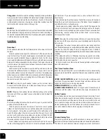
SYSTEM INSTALLATION
SEASTAR POWER ASSIST
HELM PUMP MODEL
WHEEL TURNS
WHEEL TURNS
& DISPLACEMENT
CONFIG. C
CONFIG. D
'PARALLEL'
'SERIES'
1.7 cu.in. per revolution
14.5
10
2.0 cu.in. per revolution
12.5
8
2.4 cu.in. per revolution
10.3
6
C
D
Hoses MUST be at least 6' in
length from the power assist to
the helm pump, or, from the
power assist to the cylinder(s).
NOTICE
Figure 5.
CAUTION
ALL hose connections MUST be
torqued to 15 ft-lb (20.34Nm).
DO NOT run the wires or hoses
in areas where the may come
in contact with battery acid or
excessive heat, i.e. engine
exhaust, manifolds or any
other area that may damage
the wires or hoses.
WARNING
Summary of Contents for 388CC
Page 1: ...388CC 388 Center Console OWNER ASSISTANCE MANUAL Revised 2014 ...
Page 30: ...29 Appendix 388CC ...
Page 31: ...30 ...
Page 32: ...31 Hydraulic Steering System ...
Page 33: ...32 ...
Page 34: ...33 ...
Page 35: ...34 ...
Page 39: ......
Page 105: ......
Page 122: ......
Page 157: ...8 Rotation of Ports 1 2 3 4 5 6 7 1 Rotation of Pump Head 2 3 4 5 ...
Page 160: ...GB ar com GB ...
Page 210: ...38 A B 50 mm C 20 mm ...
Page 243: ...24 SEASTAR Hydraulics ...
Page 245: ...26 SEASTAR Hydraulics ...
Page 247: ...28 SEASTAR Hydraulics ...
Page 249: ...30 SEASTAR Hydraulics ...
Page 258: ...vi Selection Guide ...
Page 264: ...1 6 Selection Guide ...
Page 268: ...2 4 Selection Guide ...
Page 294: ...4 8 Selection Guide ...
Page 344: ...11 2 Selection Guide ...
Page 360: ...T1873 Lewmar USA4 Thruster 140 to ...