30
This valve should be tested every month during periods
of boiler operation, and at the beginning and end of any
extended non-service period. Prior to testing, make cer-
tain discharge pipe is properly connected to valve outlet
and arranged so as to contain and safely dispose of boiler
discharge. Test at normal system operating pressure. Hold
the trip lever fully open for at least fi ve seconds in order to
fl ush free any sediment that may lodge on the valve seat.
Then permit the valve to snap shut.
Burner And Pilot Flame
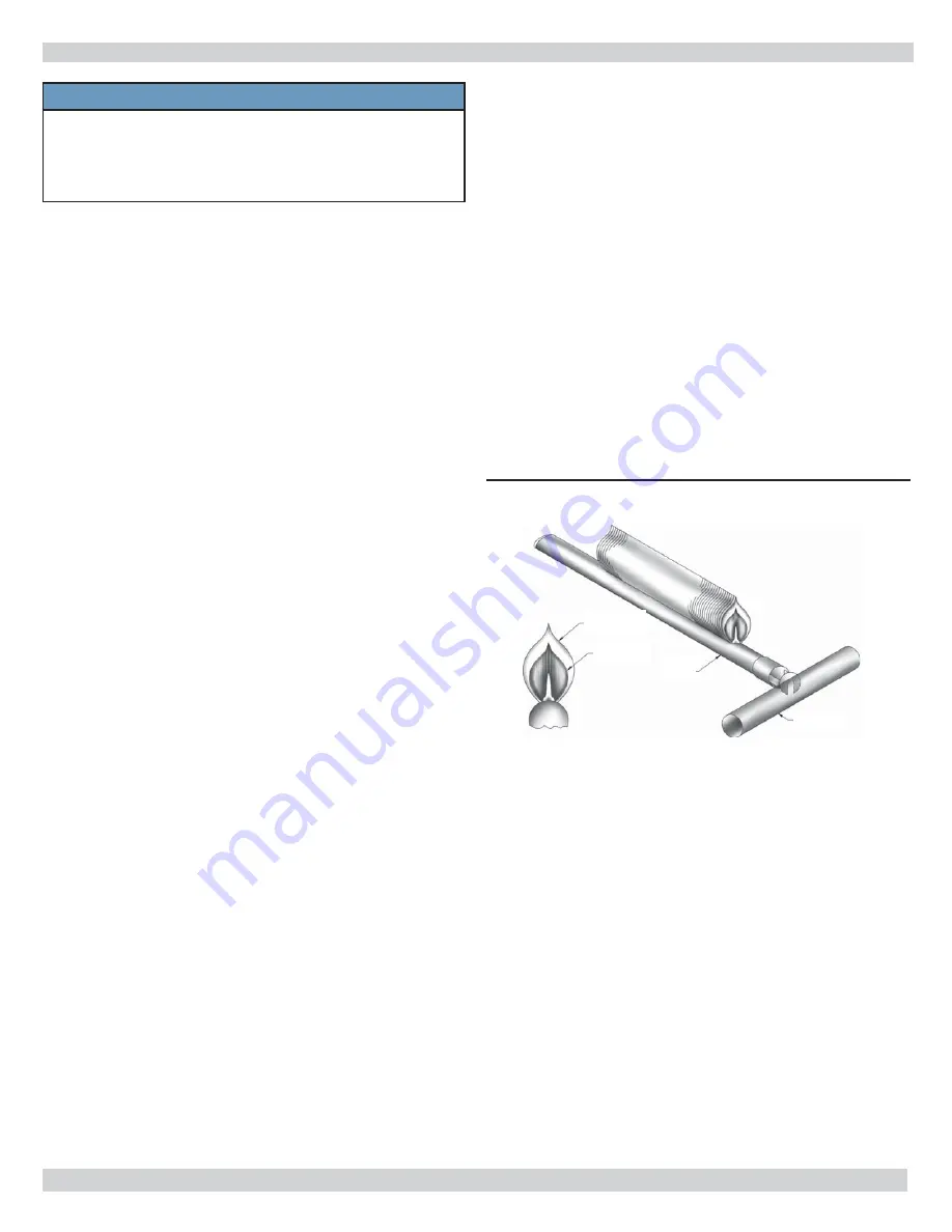
We recommend that you make a periodic visual check of
the burners and pilot fl ame,
Figure 42. During this visual
check look for any deterioration from corrosion or other
sources of the burners, pilot burners and boiler base frame.
Also be sure the boiler base interior and exterior are clean.
This visual check should be made once every month dur-
ing the heating season by the owner and once a year by
a competent service technician to assure safe and trou-
ble-free operation.
BOILER FLUE PASSAGES
Burner And Pilot Flame
Under normal operating conditions, with the burners
adjusted properly, it should not be necessary to clean the
boiler fl ue gas passages. However, to assure trouble-free
operation, we recommend that you have the fl ue passages,
burner adjustments and operation of the boiler controls
checked once each year by a competent service technician.
If it becomes necessary to clean fl ue passages, fi rst remove
the burners and pilot(s) from the boiler. Refer to Figure 13
in the Installing Draft Hood Section in the front of this
instruction and remove the clean-cut cover panel on the
draft hood.
This will expose the fl ue passages. Clean fl ue
passageways between the sections with fl exible handle
wire brush. Remove all dirt from bottom of boiler and
reassemble all parts. Be sure to check tightness of pilot
connection(s) and adjustment of pilot(s) and burner fl ames
after reassembly.
Outer Mantle
Outer Cone
Burner
Manifold
High Limit Control
While boiler is operating, set high limit control below boiler
water temperature and main burners should shut off.
Return control to normal setting and main burners should
start again.
Pressure Relief Valve
You must have pressure relief valve on the boiler. The
Relief Valve on water boilers is set at 30 psig, (50 psig
optional.) Run a pipe from the pressure relief valve
outlet to an open drain. This pipe must be of same size
as outlet on valve and open end must not be threaded.
This drain must be run in an area not subject to freezing.
Failure to do so may cause water damage or injury
should valve release.
If valve discharge occurs, or if valve fails to open as
described above, contact an authorized contractor or
qualifi ed service technician to replace the relief valve
and inspect the heating system to determine the cause,
as this may indicate an equipment malfunction.
Check Burner Input
Check boiler for proper Btu input rate.
If boiler is shut down for service, gas and electric must be
off for 5 minutes before relighting.
To check boiler for proper Btu Input proceed as
follows: With main burners operating, measure the gas
Input to the boiler by reading the meter. Be sure all other
appliances connected to the same meter are shut off.
Rate of gas fl ow (cu. ft. per hour) multiplied by the Btu
value of the gas should check with the Btu Input shown
on the nameplate of the boiler. If it is not /- 2%,
adjust Pressure Regulator to obtain the desired fl ow
(stem for adjustment is under the cap in the top of the
regulator). TURN CLOCKWISE TO INCREASE INPUT AND
COUNTERCLOCKWISE TO DECREASE THE INPUT RATE.
NOTE: The adjustment screw is plastic and may require
slightly greater turning force than metal threads.
Be sure to replace Regulator Cap.
CHECKING AND ADJUSTING
Figure 42 - Pilot and Flame
NOTICE
Do not exceed the Input rate stamped on the
nameplate of boiler located on End Jacket Panel.
Verify primary air supply to main burners is
properly adjusted for complete combustion.


