background image

13

LOCATING THE BOILER

1. Place boiler at a location as centralized to the 

piping system and as close to the chimney or vent 

terminal as possible to minimize condensation. 

At input rates up to 1.75 gph (245,000 Btu/hr), 

the  supply  and  return  from  radiation  may  be 

piped on the same end of the boiler. At higher 

rates,  it  is  recommended  that  the  supply  be 

piped from the rear of the boiler and the return 

be piped from the front of the boiler. Coordinate 

jacket  installation  with  piping.


See 

“Jacket 

Assembly  Instructions” 

and 

“Piping  Diagrams”


in this manual for more information.

2.  See 

Figure  #4

  for  installation  on  combustible 

flooring. If necessary, place metal shims beneath 

feet to ensure a level unit.

3. Accessibility clearances must take precedence 

over  fire  protection  clearances.  Allow  at  least 

24”  for  servicing  at  the  tankless  and  burner 

sides  of  the  unit. Allow  at  least  18”  at  a  side 

where  passage  is  required  for  access  to 

another side for servicing. A 6” clearance from 

combustible  material  on  all  sides  and  the  top 

is  recommended.  18”  clearance  is  necessary 

between smoke pipe and nearest combustible 

material. See NFPA 31, latest revision, for safe 

methods to reduce clearances where necessary. 

NFPA publications are available at Battery Park, 

Quincy, MA 02269.

CONSULT FIRE AUTHORITIES

FOR LOCAL REQUIREMENTS

JACKET ASSEMBLY 

(Indoor Boilers)

JACKET ASSEMBLY

 (INDOOR BOILERS)

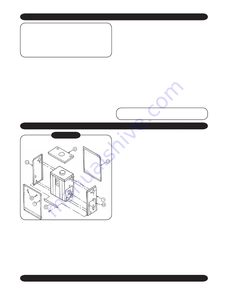
 1. See 

Figure #5

 (above) for reference. Note that 

all sheet metal screws are #10 unless specified 

otherwise.

 2. See hardware package in boiler accessory kit for 

stand-off bolts, studs, acorn nuts, washers, and 

⅛” pipe plug. Note that the sight glass assembly 

is also found in the boiler accessory kit.

 3. Screw double end stand-off bolts into castings 

next to upper supply and lower return tappings 

in both ends of the boiler. Screw three 

5

/

16

” studs 

finger-tight into burner mounting.

  4.  Hold  panels  1  and  1A  against  burner  end  of 

boiler  and  insert  necessary  piping  through 

jacket openings into boiler casting.

 5. Screw acorn nuts onto stand-off bolts.
 6. Screw 1” nipple and sight glass holder into hole 

above burner.

 7. Screw the ⅛” plug into tapping on upper left of 

burner mounting.

 8. Install panel 2 on opposite side of boiler in same 

manner as panel 1.

  9.  Install  panel  3  by  attaching  it  with  four  sheet 

metal  screws  to  panels  1  and  2  (already  in 

position).

10. Install temperature/pressure gauge into either of 

the two ¾” tappings on top of the casting. Using 

a ¾” x 4½” nipple, install relief valve in second 

top  tapping.  Install  jacket  top  panel  (#4)  by 

attaching it with four sheet metal screws to the 

three jacket side panels already in position.

To  permit  easy  disassembly  of  overflow  pipe  in 

order to raise jacket top panel for annual cleaning, 

screw hand tight a ¾” nipple into the relief valve. 

Attach a ¾” elbow to the nipple and an overflow 

NOTE: 

Please  see  the  separate  Venting 

Instruction  for  flue  size  limitation  and  other 

information  on  venting.  For  direct  exhaust 

systems, the total run of horizontal flue pipe 

must not exceed 6’ and the total run of vertical 

flue pipe must not exceed 10’.

Figure #5

Summary of Contents for ULTIMATE PF Series

Page 1: ...RESSURE FIRED WET BASE HOT WATER BOILERS An ISO 9001 2000 Certi ed Company INSTALLATION MANUAL AND OPERATING INSTRUCTIONS ULTIMATE BOILERS 85 Middle Rd Dunkirk NY 14048 www ecrinternational com P N 14...

Page 2: ......

Page 3: ...throughout this manual to notify the reader of potential hazards of varying risk levels DANGER Indicates an imminently hazardous situation which if not avoided WILL result in death or serious injury...

Page 4: ...Min Max 95 2 10 117 250 102 217 87 5 84 3 88 26 85 20 6 7 24 PFO 8T Min Max 1 25 2 75 154 324 134 282 87 4 5 88 15 5 8 8 30 WITHOUT TANKLESS COIL MODEL RECOMMENDED FIRING RATES GPH HEATING CAPACITY M...

Page 5: ...ATHERPROOF BOILERS MUST BE NON TOXIC 1 D O E Heating capacity is indicated in thousands of Btu per hour Use of antifreeze in any boiler can reduce capacity net output and ef ciency by a signi cant amo...

Page 6: ...5T 0 80 AFG 14619201 Delavan 65 X 70 A 140 F3 Fixed Yes 10 0 0 0 1 50 AFG 14619201 Delavan 1 00 X 70 A 140 F6 Fixed No 10 0 1 0 1 75 AFG 14619201 Delavan 1 50 X 70 A 140 F12 Fixed No 10 0 3 0 PFO 6T 0...

Page 7: ...van 1 35 X 60 W 160 1 5 3 PFO 5T 0 80 F5 1050006 Delavan 60 X 60 A 175 1 0 2 3 1 50 F5 1050006 Delavan 1 25 X 60 A 150 4 0 5 5 1 75 F10 14619011 Delavan 1 35 X 60 A 170 1 5 3 2 PFO 6T 0 95 F5 1050006...

Page 8: ...001448 550001451 1 70 AFG 14619202 Delavan 1 50 X 80 A 140 F12 Fixed No 222 550001448 550001451 PFO 5T 0 80 AFG 14619202 Delavan 65 X 70 A 140 F3 Fixed Yes 75 550001448 550001451 1 50 AFG 14619202 Del...

Page 9: ...pacity rated in accordance with the code of the Hydronics Institute These boilers operate on 2 Heating Oil Natural Gas or Propane Gas with the proper burner Boiler Kit Duct Dia Wall Opening 3 sections...

Page 10: ...lve will automatically open Lifting of the relief valve can discharge large quantities of steam and hot water which may damage the surroundings Before installing the relief valve read the manufacturer...

Page 11: ...boiler installations using oat type vents the air vents should be closed for normal operation If air is heard or noticed by a loss of heat purge the system and open the vents for a short period of ti...

Page 12: ...ced on a combustible oor protected with hollow masonry not less than 4 100mm thick covered with sheet metal not less than 24 gauge Such masonry shall be laid with ends unsealed and joints matched in s...

Page 13: ...heet metal screws are 10 unless speci ed otherwise 2 See hardware package in boiler accessory kit for stand off bolts studs acorn nuts washers and pipe plug Note that the sight glass assembly is also...

Page 14: ...o circumstances should automotive antifreeze be used 2 Use of antifreeze in any boiler may reduce capacity by 10 or more and increase fuel consumption Tankless coil performance will fall as concentrat...

Page 15: ...the low limit The differential control setting is typically 20 F but may be adjusted to vary the time it takes the burner to respond to a call for domestic hot water COLD STANDBY 1 Cold standby is sui...

Page 16: ...16 BURNER WIRING RIELLO BURNER WIRING...

Page 17: ...17 MULTI ZONE SYSTEM WIRING AND PIPING...

Page 18: ...18 MULTI ZONE SYSTEM WIRING AND PIPING...

Page 19: ...19 PIPING WITH CIRCULATORS MULTI ZONE SYSTEM WIRING AND PIPING...

Page 20: ...20 MULTI ZONE SYSTEM WIRING AND PIPING...

Page 21: ...LTI ZONE SYSTEM WIRING AND PIPING ZONE 3 ZONE 2 ZONE 1 PRIORITY ZONE BOILER USE FULL PORT ZONE VALVE FOR OPTIMUM TANK PERFORMANCE CONSIDER USING ZONE CIRCULATOR SEE FIGURE 5 ZONE 4 PIPING WITH ZONE VA...

Page 22: ...pressure set at 140 psi Nozzle output will be approximately 18 greater than that at 100 psi Pump pressure on Riello burners should be adjusted according to settings in Suggested Nozzles and Settings f...

Page 23: ...homeowner When outside thermostat is not used Jumper T T Terminals on relay L8181 CONTROL SETTINGS Use the following setting for the rst adjustment High Limit Set Point 180 F Low Limit Set Point 160 F...

Page 24: ...er as provided rather than a standard lter between burner and oil storage tank 12 Before making control adjustments verify that all fuel water and electrical connections have been made in accordance w...

Page 25: ...ring Wiring for zone valve installations are furnished with zone valve packages Complete installation must be made in accordance with the requirements of the local authorities and the National Fire Pr...

Page 26: ...ould be installed at a convenient location inside the building a Domestic Water Heating See Figure 14 for piping of remote indoor tankless coil or indirect water heater An indirect Water Heater is rec...

Page 27: ...2 and 3 10 Fasten L8151 control to upper right hand side of panel 4 with bulb in control well already in place 11 Install additional controls according to manufacturer s instructions included and to F...

Page 28: ...eeze See Antifreeze on this page for more information 16 Cover all outdoor piping with weather resistant insulation 17 Start burner according to manufacturer s instructions and make combustion tests I...

Page 29: ...seofantifreezeinanyboilermayreducecapacity by 10 or more and increase fuel consumption Tankless coil performance will fall as concentration of antifreeze is increased 3 Because antifreeze forms slush...

Page 30: ...the high limit control setting must be set at least 20 F above the low limit The differential control setting is typically 20 F but may be adjusted to vary the time it takes the burner to respond to a...

Page 31: ...pressure exceeds the 30 lb reading on the gauge If this pressure is exceeded and the pressure relief valve leaks water when the boiler is operating at normal pressures it should be immediately replace...

Page 32: ...fter ameout the safety switch locks out ignition stops motor stops and oil valve when used closes To restart open oil supply valve and reset safety switch Ignition Failure With burner off close oil su...

Page 33: ...pressure switch It is mounted to the jacket T T OIL FIRED Pressure Switch Flexible Tubing Hose Barb Connection Connect the exible tubing provided from the hose barb on the burner mount ing plate to th...

Page 34: ...t should be checked at least twice a year for leakage and replaced if necessary ANNUAL SERVICE CHECK To assure trouble free operation we recommend that you have the ue passages burner combustion chamb...

Page 35: ...test instruments BOILER CLEANING INSTRUCTIONS 1 Shut off all electrical power to the boiler burner and shut off fuel supply 2 Remove the sheet metal smoke pipe from the top of the boiler Inspect pipe...

Page 36: ...rner become dirty at frequent intervals after correcting the dirt condition also correct the control setting or other cause of the short cycling Check thermostat heat anticipator and correct setting i...

Page 37: ...ain the model number from the data plate on your boiler then determine the part number and description of each part from the following illustrations INCLUDED IN THIS SECTION Boiler Parts Indoor Jacket...

Page 38: ...38 BOILER PARTS...

Page 39: ...ront Chamber Cone Chamber Front Plate Durablanket Rear Chamber Front Section Push Nipples Tie Rods Flue Collector Middle Section Back Section Tankless Coil Single Pass Tankless Coil Kit Single Pass In...

Page 40: ...LEFT SIDE JACKET PANEL 42582030AC 42582030AC 42582030AC 42582030AC 42582030AC 42582030AC 5 RIGHT SIDE JACKET PANEL 42582028AC 42582031AC 42582031AC 42582031AC 42582031AC 42582031AC 6 RIGHT SIDE COVER...

Page 41: ...ON MODELS 3TW 4W MODELS 6TW 7W MODELS 7TTW 8TW 9W 1 Top Panel 14630411 14630412 14630413 2 Jacket 14630402 14630403 14630404 3 Weather Shield 14630421 14630424 14630427 4 Flue Pipe 14630423 14630426 1...

Page 42: ...OOD 240005874 2 VACUUM RELIEF DRAFT REGULATOR ASSY 3 PRESSURE SWITCH 240005625 4 VITON TUBING 30705 5 BRASS BARB 1230010 BECKETT BURNER CF375 W SIDE WALL BOOT 240006433 PRESS SWITCH WIRE HARNESS 24000...

Page 43: ...o 0012 Circulator Models 7TT 8T 9 14626062 4 1 Taco Isolation Valves 14626043 1 Flanges 14626063 5 Temperature Pressure Gauge 1260006 6 x Bushing 1060002 7 ASME Relief Valve 14622011 8 x 4 Nipple 1460...

Page 44: ......

Reviews: