18
5.4 Trim Piping
• Temperature - Pressure Gauge. Install temperature
pressure gauge. See Figures 5-1 and 5-2.
• Some boiler models may have integral drain valve located
inside jacket directly underneath pump. Install provided
external drain valve as required.
5.5 System Piping
• Ensure caps are removed from boiler water connections.
•
See Figure 5-6 for a basic system piping configuration.
•
Systems with automatic fill valves require back flow
prevention device.
• Single boiler system. See Figure 5-6 for general guidance.
Additional considerations:
• Boiler control does not accommodate central heating
pump. Installer is responsible for integration of
central heating pumps with field sourced control.
• Boiler control allows domestic hot water
prioritization. Function could be lost if central heating
pump is not directly connected to zone control system.
• Multiple boiler system. Considerations:
• Field sourced control system logic may require
equivalent water temperatures entering each boiler
to properly sequence and adjust system supply
temperature.
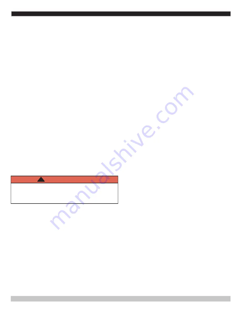
WARNING
Burn and scald hazard. Verify all plastic caps are
removed from boiler connections. Failure to follow
these instructions could result in death or serious
injury.
!
• Thoroughly flush all hydronic piping.
Flush system
(wash) clean after installing all piping. Debris or cutting
oils, etc., left inside system will reduce heat transfer in
heat exchanger. Small pieces of Teflon tape are eventually
trapped in the water pump impeller and reduce water flow
rate. Non-flushed systems have low energy efficiency and
potential boiling noise due to ineffective heat transfer and
reduced water flow rate. Flush all zones one by one, when
flushing the system.
•
Secure all valves/fittings to boiler.
• Connect system valve pipe work to the boiler.
•
Route pressure relief valve discharge piping to the floor.
Follow local code with respect to necessary distance to the
floor.
See Figure 5-2.
• Verify all valves are closed.
5 - HYDRONIC PIPING
PN 240012363 REV. A [08/31/2018]


