


6
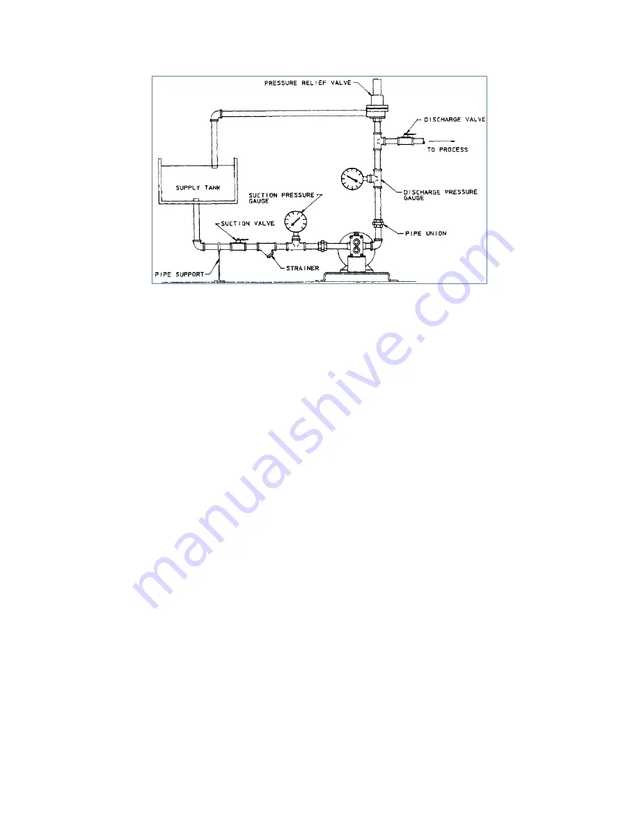
Figure 1
3. INSTALLATION
1. Pump installation site should be selected to provide easy access for routine
maintenance and to protect the pump from damage by the elements or from leaks or
drips from nearby process equipment.
2. Suction and discharge ports of Eco Gearchem pumps can be determined as follows:
A. Looking at the pump drive shaft, the suction port is to the right of the shaft,
when the shaft rotates clockwise and the drive shaft is located below
the ports for standard configuration on Model G2, G4, G6, GB and GHB.
B. Looking at the pump drive shaft, the suction port is to the left of the shaft, when
the shaft rotates clockwise, and the drive shaft is located above the ports for
standard configuration on Models GA 12 and GA 16.
C. Reversing drive shaft rotation reverses flow and thus suction and discharge ports
for all models.
3. Keep suction lines short, straight and of sufficient size to minimize friction loss to the
pump. Make sure there is sufficient suction supply, so that pump will not starve or
run dry. Flooded suction or gravity feed of fluid to pump inlet is generally preferred.
4. Use only full-bore ball valves or gate valves in the suction piping. If suction strainers
are required, size them to minimize pressure drop and select those of a type that are
easily cleaned.
5. Arrange all suction piping and fittings to prevent formation of air pockets. Make sure
all joints are tight.
6. Flush and blow out all suction lines prior to mating up to pump. Use nipples and
unions, or spool pieces with flanged pumps, for ease of maintenance.
7. Do not spring piping, either suction or discharge, when mating up to pump. Use
supports or hangars at intervals as required. When necessary, provide for thermal
expansion and contraction so that no strain is placed upon the pump.
8. Check carefully alignment of pump and motor or drive system. Improper alignment is
one of the most common causes of seal and stuffing box problems, as well as a
major cause of rapid bearing wear and eventual pump failure.
9. Check all bolts and nuts for tightness. Correct any conditions which could cause
destructive vibration or leakage.
10. Where required, provide proper system for seal flush, and/or drain. Observe any
special instructions for packing lubrication.
11. If start-up screens are used be sure they do not clog and starve suction. Start-up
screens should be removed prior to placing system into regular operation.
Summary of Contents for GA Series
Page 18: ...18 8 PUMP SPECIFICATION CHART...
Page 19: ...19 9 EXPLODED VIEW DRAWING G2 G4 SERIES...
Page 20: ...20 10 EXPLODED VIEW DRAWING G6 G8 SERIES...
Page 21: ...21 11 EXPLODED VIEW DRAWING GH8 SERIES...
Page 22: ...22 12 EXPLODED VIEW DRAWING GA12 GA16 SERIES...
Page 23: ...23 13 SEAL ARRANGEMENT DRAWINGS...
Page 24: ...24...
Page 25: ...25...
Page 26: ...26...
Page 27: ...27...
Page 29: ...29 15 GEARCHEM PUMP PRESSURES...
Page 30: ...30...
Page 32: ...32...
Page 33: ...33...
Page 35: ...35 15 PUMP PERFORMANCE CURVES...
Page 36: ...36...
Page 37: ...37...
Page 38: ...38...
Page 39: ...39...
Page 40: ...40...
Page 41: ...41...
Page 42: ...42...
Page 43: ...43...
Page 44: ...44...
Page 45: ...45...
Page 46: ...46...
Page 47: ...47...
Page 48: ...48...
Page 49: ...49...
Page 50: ...50...
Page 51: ...51...
Page 52: ...52...
Page 53: ...53...
Page 54: ...54...
Page 55: ...55...
Page 56: ...56...
Page 57: ...57...
Page 58: ...58...