background image


11 


7.1.2 DHCP (Dynamic Host Configuration Protocol) 

If you are using switch or LAN where DHCP server is enabled, changing the IP manually 
is not necessary because DHCP server will automatically assign a unique IP address to 
each device. 


7.1.3. Network Requirements 

Transmitters create continuous multicast streaming traffic of video on the network; for 
this  reason,  when  possible,  it  is  recommended  to  create  an  independent  IP  video 
network using managed network switches. Use of gigabit switches with jumbo frame 
and  IGMP  support  is  required  and  will  create  the  most  appropriate  scenario  for  both 
independent IP video networks, and cases where IP video systems are included within 
your data network. 

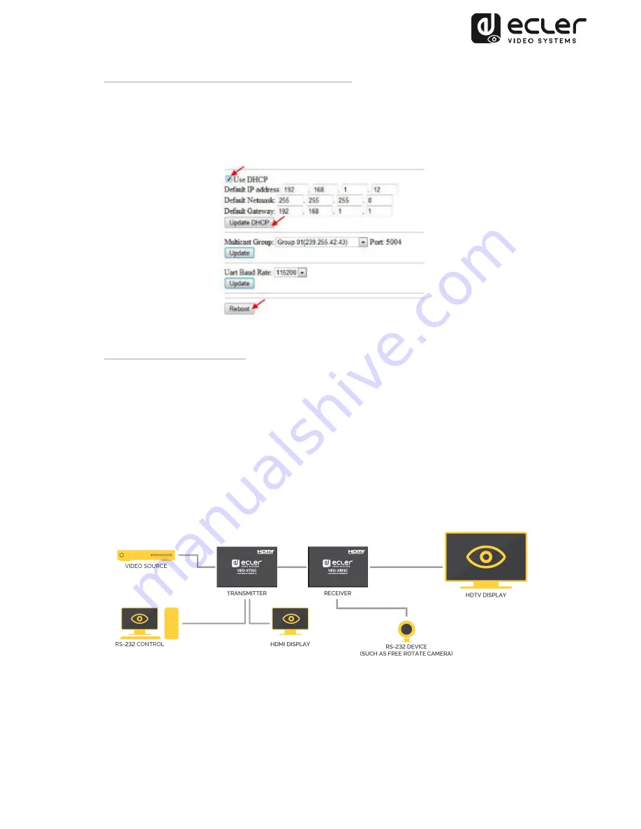
7.2. Point-to-Point Connection and Operation 


1.


Connect source device to the VEO Transmitter HDMI port. 

2.


Connect Transmitter HDMI looping output to HDMI display. 

3.


Connect remote HDMI display to the VEO Receiver HDMI port output. 

4.


Connect Transmitter and Receiver with Cat5e/6 cable 

Summary of Contents for VEO-XRI1C

Page 1: ...v 20190301 VEO XTI1C VEO XRI1C VIDEO DISTRIBUTION OVER IP H 264 Full HD over IP Video Extenders USER MANUAL ...

Page 2: ... and Rear Panel 9 6 3 IR Sensor and IR Blaster connection 10 7 INSTALLATION AND CONFIGURATION 10 7 1 IP Address Settings 10 7 1 1 Static IP Address Configuration 10 7 1 2 DHCP Dynamic Host Configuration Protocol 11 7 1 3 Network Requirements 11 7 2 Point to Point Connection and Operation 11 7 3 Point to Multipoint Connection and Operation 12 7 4 Multipoint to Multipoint Connection and Operation 13...

Page 3: ...8 1 3 Special Functions 15 8 2 Group ID and RS 232 baud rate Selection using Web Browser 15 Transmitter ID Group 15 Receiver ID Group 16 Transmitter and Receiver RS 232 baud rate 16 8 3 Group ID Selection using Telnet 16 9 PC UTILITY SOFTWARE 17 10 HOW TO RECEIVE STREAMING WITH VLC 19 11 FACTORY RESET 21 12 TECHNICAL SPECIFICATIONS 22 ...

Page 4: ...ked with symbol of may be of sufficient magnitude to constitute a risk of electric shock The external wiring connected to the terminals requires installation by an instructed person or the use of ready made leads or cords WARNING To prevent fire or shock hazard do not expose this equipment to rain or moisture WARNING An apparatus with Class I construction shall be connected to the main socket outl...

Page 5: ...ifier will be stopped but fully disconnecting the device from mains is done unplugging the power cord from the mains input socket For this reason it always shall remain readily operable 15 Equipment is connected to a socket outlet with earthing connection by means of a power cord 16 The marking information is located at the bottom of apparatus 17 The apparatus shall not be exposed to dripping or s...

Page 6: ...able in a point to point topology or standard 100m Ethernet connection in point to multipoint and multipoint to multipoint over standard Ethernet switch The over IP solutions are widely suitable for various applications such as meeting rooms classrooms commercial and residential AV systems Digital Signage systems medical information systems transportation and mall advertisement Features Supports p...

Page 7: ...GE CONTENTS VEO XTI1C Package 1 x H 264 Transmitter 1 x IR Remote control 1 x Local IR Receiver Cable 1 x IR Blaster Cable 2 x Mounting Ears 4 x Screws 1 x Phoenix plug for RS 232 cable termination 1 x 5V 1A International Power Supply 1 x User Manual VEO XRI1C Package 1 x H 264 Receiver 1 x IR Remote control 1 x Local IR Receiver Cable 1 x IR Receiver Cable 2 x Mounting Ears 4 x Screws 1 x Phoenix...

Page 8: ...us LED Indicator 3 Power Supply LED Indicator 4 HDMI local loop Output port 5 HDMI Input Port 6 RJ45 Ethernet Port 7 IR Blaster Port 8 Bi directional RS 232 port 9 Local IR Receiver Port 10 Group ID channel Display 11 Group ID decrement button 12 Group ID increment button 13 Factory reset button ...

Page 9: ... Indicator 3 Power Supply LED Indicator 4 HDMI Output port 5 RJ45 Ethernet Port 6 IR Receiver Port 7 Bi directional RS 232 port 8 Local IR Receiver Port 9 Group ID number LED Display 10 Group ID number decrement button 11 Group ID number increment button 12 Factory reset button ...

Page 10: ... Address Settings 7 1 1 Static IP Address Configuration When static IP addresses are required the IP address of each device needs to be set manually The default IP address for transmitters and receivers is VEO XTI1C 192 168 1 11 VEO XRI1C 192 168 1 12 The IP address can be changed using the embedded web page or using the utility software For web page access be sure that PC and VEO devices are in t...

Page 11: ...mended to create an independent IP video network using managed network switches Use of gigabit switches with jumbo frame and IGMP support is required and will create the most appropriate scenario for both independent IP video networks and cases where IP video systems are included within your data network 7 2 Point to Point Connection and Operation 1 Connect source device to the VEO Transmitter HDM...

Page 12: ...ect HDMI looping output of the VEO Transmitter to a local HDMI display 5 Connect Transmitter to network switch router using Cat5e or Cat6 cable 6 Connect all VEO Receivers and network switch router using Cat5e 6 cables 7 Connect HDMI displays to the HDMI VEO Receiver units with HDMI Cable 8 Connect IR TX cable to IR TX port of the transmitter Connect IR RX cable to IR RX port of the receiver Then ...

Page 13: ...nsmitter Connect IR 9 RX cable into IR RX port of the receiver Then you can control source at the RX side with IR 10 Connect RS 232 cable from the PC or automation system to the RS 232 port of the Transmitter Connect RS 232 cable from the Receiver to the RS 232 device to be controlled 11 Power on Transmitter and Receiver with adapter 5V 1A and power the switch In case the switch supports PoE Power...

Page 14: ...The Group ID can be selected in three different ways Using the IR Remote Control Via Web browser Using Telnet 8 1 Group ID and RS 232 baud rate selection using IR Remote Control 8 1 1 Group ID The Group ID can be selected using the included IR remote control Ensure that IR Ext sensor is connected refer to 5 1 The remote control can be used to change Group ID or RS 232 baud rate as explained below ...

Page 15: ...or more than 3 seconds will allow to factory reset the VEO devices The LED display will start blinking and when it shows 00 the factory reset is successfully completed 8 2 Group ID and RS 232 baud rate Selection via Web Browser When PC is connected to the same network as the VEO devices and it is in the same domain the Group ID number of each device can be selected using the web page as well as RS...

Page 16: ...Transmitter Receiver and third party RS232 devices are the same The default baud rate of Transmitter and Receiver is 2400 but it can be changed through web page by selecting the desired value from 2400 to 115200 bps The RS 232 pass through works only when the same ID Group is selected 8 3 Group ID Selection via Telnet The ID group can also be selected by opening a Telnet session with a standard Te...

Page 17: ...con to open software The Device Scan Page will appear Press the Start Scan button to search for devices on the network Using TX Setup Page and RX Setup Page it is possible to modify several settings and parameters such as Device Name Network Settings Video Bitrate Downscaling options RS 232 baudrate Group ID and perform a Device Reboot or a Factory Reset from remote ...

Page 18: ...18 After making any changes please remember to press the Update button to save new settings ...

Page 19: ... the Transmitter and PC are on the same network domain 2 Connect HDMI Source without HDCP to the Transmitter HDMI input and Power on the device 3 Connect transmitter to the network 4 Check the multicast IP address related to the selected ID Group on the Transmitter Setting web page refer to 7 2 5 Open the VLC media Player click Stream Network Input UDP 239 255 42 42 5004 6 Click Next ...

Page 20: ...20 7 Choose RTP MPEC Transport Stream or UDP 8 Click Next 9 Click Stream ...

Page 21: ...Y RESET The VEO Factory reset can be performed using the PC Utility Software 8 using the remote control 7 1 or by pressing the reset button on the device for 10 seconds using a tiny pin while the unit is powered on The default IP Address and all the factory parameters will be restored ...

Page 22: ...e Network Streaming bitrate Up to 15Mbps per stream Video latency 300 500 mS depending on network conditions Default IP TX 192 168 1 11 RX 192 168 1 12 Audio Formats LPCM 2 0 Sample Rate 48kHz Bitrate 24 bit HDMI Distance up to 10 meters 33 feet with Ecler VEO cables IR supported bandwidth 38 56 KHZ Operating Temperature 5 C 35 C 41 F 95 F Humidity 5 90 RH no condensation Power Consumption 3W Maxi...

Page 23: ...to production tolerances NEEC AUDIO BARCELONA S L reserves the right to make changes or improvements in the design or manufacturing that may affect these product specifications Motors 166 168 08038 Barcelona Spain 34 932238403 information ecler com www ecler com ...

Reviews: