32
Design Issues
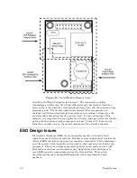
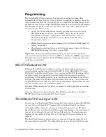
Figure 16
. Control Module Keepout Areas
Area #3 is the “High Voltage Isolation Area.” The transceiver coupling
transformer on all Neuron 3150 Control Modules provides electrical isolation
between the control module’s local ground (primary side) and the network wiring
(secondary side). The transformers and associated filter components are
designed to withstand moderately large primary-to-secondary voltages (see the
control module data sheets for the exact ratings). To take advantage of this
isolation, it is important to keep application circuitry, logic ground, metal chassis
parts, and other primary-side components at least 3.8 mm (0.15 inches) away
from the secondary area on the control module and the network connector.
ESD Design Issues
Electrostatic Discharge (ESD) is encountered frequently in industrial and
commercial use of electronic systems. Reliable system designs must consider the
effects of ESD and take steps to protect sensitive components. Static discharges
occur frequently in low-humidity environments when operators touch electronic
equipment. The static voltages generated by humans can easily exceed 10 kV.
Keyboards, connectors, and enclosures provide paths for static discharges to
reach ESD-sensitive components such as the Neuron Chip. This section
describes techniques to design ESD immunity into control module-based
products.
Summary of Contents for LONWORKS FT 5000
Page 1: ...LONWORKS Twisted Pair Control Module User s Guide 078 0015 01F...
Page 18: ...10 Mechanical Considerations Figure 5 Neuron 3150 Control Module Mechanical Footprint...
Page 20: ...12 Mechanical Considerations Figure 8 Vertical Component Profile for the Control Modules...
Page 22: ......
Page 26: ......
Page 34: ......
Page 55: ...www echelon com...


