LonWorks Twisted Pair Control Module User's Guide
23
transceivers, or TPM-1250 SMX transceivers to eliminate the possibility of
reflection-related transmission failures.
No such topology rule applies to the
use of TP/XF-78 control modules, TPT/XF-78 transceivers, or TPM-78
SMX transceivers.
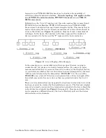
Referred to as the “8-in-16” topology rule, this rule requires that no more than 8
TP/XF-1250 Control Modules, TP/XF-1250 Transceivers, or TPM-1250 SMX
Transceivers be located within any 16 meter length of cable. This means that no
matter where along the bus the 16 meter measurement is taken, there should be
no more than 8 devices.
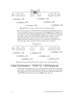
provides a diagram of such a measurement
technique. In the figure, the numbers in the boxes represent the number of
devices connected to the bus and the “T” represents the bus termination.
Figure 11
. 8-in-16 Topology Rule Example
In the example, we see an installation with six groups of devices, varying in
number from 2 to 8 devices, in a doubly terminated bus. By using a 16 meter
measurement stick that we can move from side-to-side over the length of the bus,
we can determine whether the 8-in-16 rule has been met (designated by the word
“OK”) or violated (shown by the designation “PROBLEM”). In the case of the
PROBLEM area, a total of 13 devices are located within a 16 meter length of the
bus, which amounts to five more devices than are permitted under the 8-in-16
rule.
There are two solutions that can be applied to situations in which the 8-in-16 rule
has been, or must be, violated by the installation scenario. The first and simplest
remedy is to insert a router and two termination networks in the bus to break the
network into two channels (see
on page 24). Because each side of the
router comprises a different channel, the bus is effectively split and the devices
divided between two channels.
Summary of Contents for LONWORKS FT 5000
Page 1: ...LONWORKS Twisted Pair Control Module User s Guide 078 0015 01F...
Page 18: ...10 Mechanical Considerations Figure 5 Neuron 3150 Control Module Mechanical Footprint...
Page 20: ...12 Mechanical Considerations Figure 8 Vertical Component Profile for the Control Modules...
Page 22: ......
Page 26: ......
Page 34: ......
Page 55: ...www echelon com...

