


2
Electrical Interface
FT 5000 Control Module
The following sections describe the electrical interface for the FT 5000 Control
Module.
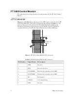
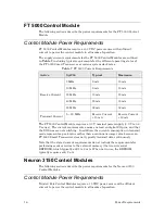
JP1 Connector
and
JP1
header connector for the FT
5000 Control Module. The I/O pin function names defined in
same as those used in the
Series 5000 Chip Data Book
, which defines the
functions and electrical characteristics for the signals. The I/O signals are
connected directly to the FT 5000 Smart Transceiver without buffering.
M
OV_GN
D
IO2 IO0
C
P
2_
T
X
LE
D
SVC
-
RS
T-
FT_
NE
TA
IO
10
IO8 IO6 IO4
SC
L
SD
A_C
S1-
IO
11
FT_
NE
TB
IO3 IO1
IO5
IO9 IO7
VDD3V3
C
P
3_
R
X
LE
D
JP1
HEADER 13X2
2
4
6
8
10
12
14
16
18
20
22
24
26
1
3
5
7
9
11
13
15
17
19
21
23
25
Figure 1
. FT 5000 Control Module JP1 Connector
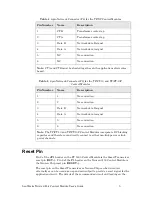
Table 2
. FT 5000 Control Module JP1 Connector
Pin Number
Signal Name Description
1
GND
Ground
2
RST~
Reset (active low)
3
CP3_RXLED
RxActive for network activity LED
4
CP2_TXLED
TxActive for network activity LED
5
NC
No Connect
6
VDD3V3
3.3 V Input Power
7
GND
Ground
Summary of Contents for LONWORKS FT 5000
Page 1: ...LONWORKS Twisted Pair Control Module User s Guide 078 0015 01F...
Page 18: ...10 Mechanical Considerations Figure 5 Neuron 3150 Control Module Mechanical Footprint...
Page 20: ...12 Mechanical Considerations Figure 8 Vertical Component Profile for the Control Modules...
Page 22: ......
Page 26: ......
Page 34: ......
Page 55: ...www echelon com...


