7
4.6
REASSEMBLY
(Refer Section 5
– Parts Designation)
4.6.1 Pump
1. Fit liner to body ensuring correct orientation. (Liner is
located using the key which is pinned to the body, the
word "OUT" is cast into the liner and this must be
towards the discharge port area..
2. Fit one wearplate to one end of the body ensuring body
key locates in slot in wearplate. Fit body cover with new
O-Ring to secure wearplate.
3. Assemble three lower vanes in the rotor and whilst
cradling these to prevent them dropping out, insert the
three pushrods into the rotor.
NB:
Vanes must be correctly oriented i.e. the rounded ends
of the vanes contact the liner and the slots in the face of
the vanes
must lead
the direction of rotation.
4. Insert the rotor/shaft/vane/pushrod assembly into the
body and then insert the other three vanes ensuring
correct orientation.
5. Fit wearplate to other end of body, ensuring body key
locates in slot in wearplate.
6. Fit body cover with new O-Ring.
7. Fit rotating components of mechanical seal assemblies
to each end of shaft.
NB:
Ensure mechanical seal components are clean prior to
assembly, lubricate before fitting and ensure that O-Rings
locate correctly on shaft and that slots in seal assembly
locate over drivepins in shaft.
8. Fit O-Rings to stationary seal faces, lubricate and fit
stationary seal faces to bearing housings taking care to
ensure that location pins locate in holes provided in
bearing housings. Place seal failure O-Rings in bearing
housings inside stationary seal faces.
9. Fit O-Rings to bearing housings.
10. Carefully fit bearing housings over shaft and fasten to
body covers.
NB:
When fitting bearing housings, ensure that seal failure
O-Rings are not dislodged. Seal failure O-Rings must
remain captive between bearing housing and stationary
seal face.
11. Fit bearing dampening O-Ring to each end of shaft and
slide along shaft until seated in groove.
12. Fit ball bearings over shaft and into bearing housings.
13. Fit lockwashers and locknuts to shaft.
NB:
Do not tighten locknuts at this stage.
Lockwashers must not be
reused as bending the tabs
more than once may cause fatigue which could result in
failure and/or major pump damage. Only reassemble
with new lockwashers of the correct thickness (Refer
parts list)
TO SET AXIAL CLEARANCES IN PUMP:
14. While rotating shaft by hand using a suitable handle,
tighten inspection end locknut until rotor/shaft assembly
locks. At this point, the end of the rotor should be hard
against the wearplate.
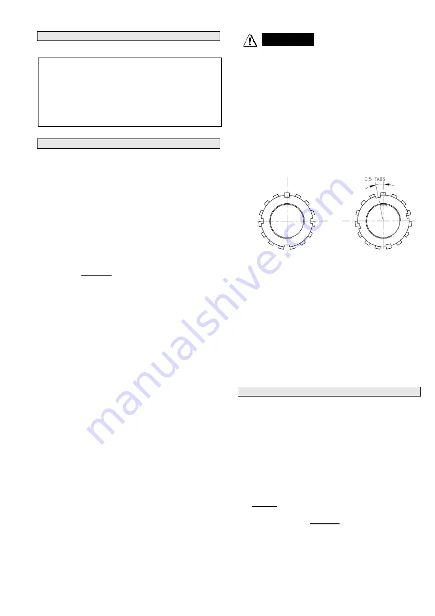
15. Back off the inspection end locknut 0.5 (one half) tab
–
(see diagram) then, if necessary back it off slightly
further (
only as far as required to align a locking tab
).
Lock in this position with tab of lockwasher
Fig 3
16. While turning shaft, tighten drive end locknut until an
increase in drag is felt (pre-loading), indicating that ball
bearings are tightly clamped.
17. Back off drive end locknut just enough to allow free pump
rotation while maintaining some pre-loading on drive end
ball bearing. Then if necessary back it off slightly further
(
only as far as required to align a locking tab
) Lock in
this position with tab of lockwasher.
18. Fit dust covers to both ends of pump with new seal in
drive end dust cover.
19. Fit grease nipples and pressure release plugs to the
bearing housings.
4.6.2 Pressure Relief Valve
1. Screw adjusting screw fully into spring cap and fit O-
Rings to spring cap and valve cover.
2. Lubricate bore of valve cover and insert spring cap
partially into valve cover.
3. Fit valve, spring and valve cover assembly to body and
fasten into position.
4. Use a 6mm allen wrench to adjust pressure relief valve
setting.
NOTE:
Clockwise movement of the adjusting screw
reduces spring tension thus reducing differential
bypass pressure. Anticlockwise movement of the
adjusting screw increases spring pressure thus
increasing differential bypass pressure.
Never set differential bypass pressure above 1050 kpa
(150psi)
5. After adjustment, replace flush plug in valve cover.
Pump Fastener Torque settings:
V2000 V3000/V3010 V3010
Body Material
DI
DI
AL
Body Cover to Body
77Nm
77Nm
77Nm
Valve Cover to Body
44Nm
44Nm
30Nm
Brg Housing to Body Cover
44Nm
44Nm
44Nm
Dust Cap to Brg Housing
2Nm
2Nm
2Nm
Adapter Flange to Body
44Nm
44Nm
30Nm
Suction Flange (CL 300)
Dependent
on
Gasket
(DI=Ductile Iron, AL=Aluminium))
WARNING
ER
Summary of Contents for V Series
Page 9: ...9...
Page 12: ...12 NOTES...


