4
SECTION 2
– INSTALLATION
Installation and removal of this
equipment
should
be
performed by suitably qualified competent personnel in
accordance with
relevant Directives, Standards, Codes,
Regulations
and site restrictions - in conjunction with
these instructions
.
Never loosen or remove fittings,
flanges,
etc.
while
under
pressure (vapour pressure of
LPG may be very high), always isolate components or
pipework and depressurise prior to work.
2.1
LOCATION
The pumping unit should be placed as close as practicable
to the source of supply keeping within the NPSHr of the
pump. Ensure floor area and headroom allotted are sufficient
for inspection and maintenance. Allow sufficient space and
ventilation for motor cooling requirements. Be sure to allow
for crane or hoist access if required.
2.2
FOUNDATIONS
Baseplate units should be accurately installed. When on a
concrete foundation, ensure that it has been poured on a
solid footing.
2.3
PUMP PIPING CONNECTIONS
NOTE:
Never draw piping into place by use of force at
the port connections of the pump.
All piping should be supported independently and line up
accurately with the pump ports.
2.4
STRAINER PROTECTION
The pump suction should always be protected by an efficient
suction strainer of adequate size to accommodate the liquid
viscosity conditions without causing excessive suction
resistance.
2.5
COUPLING ALIGNMENT
To maximise the life of the pump appropriate alignment of the
coupled shafts is a fundamental requirement of any coupling
installation.
NOTE
: Coupling types must be selected and installed in
compliance with the relevant Directives, Standards,
Codes, and Regulations dependant on application and
location. (e.g. ATEX compliant
– if applicable)
Reference should be made to OEM coupling data for
specific requirements however angular misalignment and
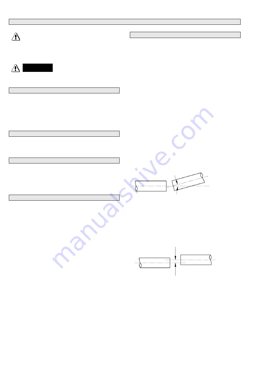
parallel misalignment as shown in Figs 1 & 2 must be
corrected.
If pump was supplied by Ebsray as part of a pumpset unit,
pump and driver have been accurately aligned at factory.
When incorporating these pumps into other equipment,
manufacturers should ensure that coupling alignment is
properly addressed.
To ensure that alignment has been maintained during transit
and installation, alignment MUST BE CHECKED upon final
installation and prior to startup.
Ensure ‘distance between shaft ends’ (DBSE) is correct for
the type of coupling utilised.
ANGULAR MISALIGNMENT as shown in Fig.1 where
shafts are at an angle to one another should be corrected
before parallel misalignment.
Fig 1
PARALLEL MISALIGNMENT as shown in Fig.2 where
shafts are in line angularly and parallel to each other but
are offset can now be corrected.
Adjustment by use of shims under the driver (or pump) will
effectively correct error in the vertical plane.
Movement of one of the ends horizontally will correct error
in the horizontal plane
Fig 2
.
CAUTION
DANGER
DANGER
Summary of Contents for V Series
Page 9: ...9...
Page 12: ...12 NOTES...


