Installation
48
10/13 MN03402007Z-DE/EN
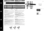
Device settings
X
Set the ZEB overload relay to the rated current of the
motor (according to the name plate or the type approval
certificate of the motor).
X
Set the tripping CLASS of the ZEB overload relay via the
device DIP switch.
X
Set the Reset DIP switch in position M to activate the
manual reset.
X
Set the Phase DIP switch in position ON to activate the
phase lost / phase imbalance detection.
Test of the auxiliary
contact
X
Check the wiring of the auxiliary contact 95/96, 97/98 to
the contactor by pulling the TRIP-button. This simulates
the tripping of the overload relay. The control circuit to the
coil of the contactor has to be interrupted by this action.
The main circuit to the motor has to be interrupted by the
switched off contactor.
X
After the Test button is released, the overload relay must
be reset in the same way as after a trip.
Operational status signaling
After switching on of the motor, the overload relay signalizes
the operating state via the integrated staus-LED. The LED
signalizes the operating state of the relay in three following
ways:
Table 12:
Status-LED
State of the Status-LED
Meaning
off
• The relay is off.
• There is no motor current.
• The motor current is lower than the lowest possible setting
(lowest value on the current setting dial).
flashing (0,5 Hz)
• The relay is working.
• The motor current is lower than 1.15 x I
r
.
flashing (1 Hz)
• The relay is working.
• The motor current is higher or equal 1.15 x I
r
(i.e. overcurrent).