Woodward SEG MRM3-2, Manual
The Woodward SEG MRM3-2 is a high-quality manual voltage regulator designed for precise control and protection of generators. Ensure optimal performance by downloading the free manual from manualshive.com for step-by-step instructions on installation and operation. Keep your equipment running smoothly with this reliable product.
Share
Download


Reviews:
No comments
Related manuals for SEG MRM3-2

EMT6
Brand: Eaton Compressor Pages: 4

SR3C
Brand: Zander Aachen Pages: 4

ICR51A
Brand: GE Pages: 16

IAV54E
Brand: GE Pages: 32

IBCG51E21
Brand: GE Pages: 16

IFC51A AND 518
Brand: GE Pages: 36

IBCG51M
Brand: GE Pages: 50

P741
Brand: GE Pages: 560

IFC66CD
Brand: GE Pages: 2

SW32V
Brand: ZIEHL Pages: 22

FW-R1P
Brand: F&F Pages: 7

ECD
Brand: Ampcontrol Pages: 29

PCS-516 DUO
Brand: F&F Pages: 11

BASICR3
Brand: Sonoff Pages: 52

PRO 1
Brand: Shelly Pages: 17

CPR 126
Brand: MULTISPAN Pages: 4

K8AB-AS
Brand: Omron Pages: 12
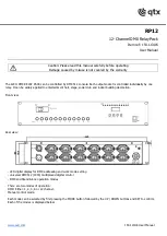
RP12
Brand: Qtx Pages: 4


