GE IFC51A AND 518, Instructions Manual
The GE IFC51A and 518 Instructions Manual is a valuable resource for users of these products. Easily accessible for download from manualshive.com, this manual provides step-by-step instructions and guidance. Get your free manual today and discover how to maximize the potential of your GE IFC51A and 518 devices.
Share
Download


Reviews:
No comments
Related manuals for IFC51A AND 518

R7M-RR8
Brand: M-system Pages: 4

Cooper Power Systems RLY-800
Brand: Eaton Pages: 14

MS220C
Brand: ZIEHL Pages: 8
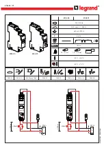
CX3
Brand: LEGRAND Pages: 2

Cutler-Hammer D64RP14 Series
Brand: Eaton Pages: 18

ZW7 Series
Brand: Eaton Pages: 3

980014
Brand: YewdaleDefiant Pages: 8

SafeHome PT180LV
Brand: PNI Pages: 8

RECA/E4
Brand: Dossena Pages: 4

DER3B-DUAL Series
Brand: Dossena Pages: 4

SR131A
Brand: Omron Pages: 8

G3PC
Brand: Omron Pages: 8

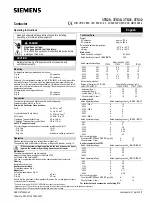
LZS PT Series
Brand: Siemens Pages: 6

SIRIUS 3RR224 Series
Brand: Siemens Pages: 14

3UA50
Brand: Siemens Pages: 4
3TS30
Brand: Siemens Pages: 5

3RS1800
Brand: Siemens Pages: 2

3RB2483-4AA1
Brand: Siemens Pages: 12


