2
Technical Data
PR211-183-505-01
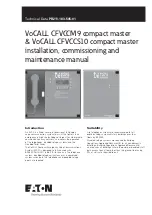
VoCALL CFVCCM9 compact master
EATON
www.eaton.com
Product overview
A VoCALL Compact unit (EVCS) comprises of two functional
blocks; the master handset and outstations (type A, type B, duo,
jack points or disabled toilet alarm), with the quantities of these
basic units being adjusted to suit the application, a maximum of
19 outstations can be used for this system. Other sized VoCALL
EVCS systems are available.
The VoCALL Compact unit (EVCS) has been designed on a star
topology. In most cases this will reduce the cable requirements
compared to all ring based systems. The topology consists of
spurs, with each spur consisting of 1 off 2 core 1mm CSA cables
(see Cable Guidance for VoCALL Network and Outstations section
for cable type). Each spur can be up to 500m.
Important safety information
This equipment must only be installed and maintained by suitably
skilled and competent person. This equipment is defined as Class
1 in EN60065 (Low Voltage Directive) and must be earthed.
CAUTION
INDOOR USE ONLY
WARNING
SHOCK HAZARD- ISOLATE BEFORE OPENING
WARNING
TO REDUCE THE RISK OF FIRE OR ELECTRIC SHOCK,
DO NOT EXPOSE THIS UNIT IN RAIN OR MOISTURE
WARNING
THIS UNIT MUST BE EARTHED
WARNING
NO USER SERVICEABLE PARTS
Each VoCALL Compact unit requires a 3A spur, returning to a
breaker clearly marked EVCS DO NOT TURN OFF. If the units
are distributed around a site it is essential all units are on the
same mains phase as they are classified TEN 230V, powering
from different phases can mean a 440V potential can be present
in a unit during a major fault incident.
Anti-static handling guidelines
Make sure that electro-static handling precautions are
taken immediately before handling PCBs and other static
sensitive components.
Before handling any static-sensitive items, operators should get
rid of any electrostatic charge by touching a sound safety earth,
such as a radiator. Always handle PCBs by their sides and avoid
touching any components. PCBs should be stored in a clean, dry
place that is free from vibration, dust and excessive heat.
Storing the PCBs in a suitable cardboard box will also guard
them against mechanical damage.
Unpacking the VoCALL CFVCCM9
compact master unit
Remove the VoCALL Compact unit from its packing, and check
the contents against the following list:
1. VoCALL CFVCCM9 Compact Master unit.
2. Installation & maintenance manual (this document).
3. User guide & logbook.
4. Accessory pack with the following contents:
a. Spare mains fuse.
b. 2.5mm AF ALN key.
Using the ALN key supplied, open the right hand front cover.
Verify the following items are present:
1. 9 off outstation line connectors
2. 1 off 2 way fault connector
3. 1 off 2 way in use connector
4. 1 off 2 way access connector
5. 1 off 4 way network connector
If there are any Items missing please contact your supplier or
Cooper Safety Fire Systems, quoting the unit serial number, and
the name on the packing list enclosed so we can rectify
the situation.


