6
Technical Data
PR211-183-505-01
VoCALL CFVCCM9 compact master
EATON
www.eaton.com
Auxiliary connections
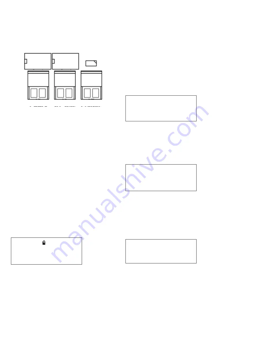
The VoCALL Compact unit has three auxiliary connections as
shown below:
Fault
In-Use
Enable
Fault:
Is a normally closed volt free relay (30V DC 1A)
which OPENS on any fault, including loss of power.
In Use:
Is a normally open volt free relay (30V DC 1A)
connection which closes when any outstation
is operated.
Enable:
Is a normally CLOSED input and is required to
operate the system (if Jumper J1 is in place then
no connection is required at the terminals.
2
ND
Fix
Replace the front panel door plate by attaching the ribbon
cable lead and fixing with the door hinges.
Attach all plugs ensuring they fit squarely into the connectors.
Do not connect battery until the master has been powered
up on mains.
Powering UP
Carefully check the outstation wiring then apply AC power to each
VoCALL Compact master unit - DO NOT commission on batteries
as the power supply has a large reservoir capacitor which may
rupture the battery fuse if the AC is not present when powering
up the system. Once the system is powered, the battery leads
can be attached to the battery.
VoCALL CFVCCM9 programming
Status screen menu
Cooper fire
Compact M9
-Healthy- Calls
0
10:24:01 07|01|11
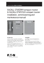
On power up, or by pressing the * key, the Status Screen Menu
can be accessed.
The top line can be changed from the Set Site Name Menu. The
second line can be changed from Set Panel Name Menu. The
third line contains the status of the unit. The fourth line shows the
current time and date.
The padlock in the top right of the display shows the state of the
write protect jumper on the rear of the display PCB. This should
be UNLOCKED to commission the system, and then LOCKED to
prevent any unauthorised changes to the commissioned system.
Menu structure
There are 3 levels of accessibility: User, Manager, and Engineer.
•
User level is accessible to all.
•
Manager level is accessible to those who log in as Manager
or Engineer.
•
Engineer level is accessible to those who log in as Engineer.
To access the menus from the Status Screen Menu, press the
TICK button.
ote:
N
If panel is installed in a public area, then all operations will be
restricted to Manager or Engineer only, except for user menus only.
This includes receiving and initiating calls.
User menu
>Log in
Accept faults*
View current faults*
View fault log*
View event log*
View call log*
View panel version
Back
ote:
N
Items marked * can be configured to display or not at user level
(see later).
Manager menu
>Log out
Accept faults
View current faults
View fault log
View event log
View call log
View panel version
Set time+date
Change manager PIN
Engineer menu
>Log out
Accept faults
View current faults
View fault log
View event log
View call log
View panel version
Set time+date
Change manager PIN
Change engineer PIN
Log settings
Panel settings
Set site name
Set panel name
Relay settings
Set service date
Panel test
Outstn settings
Network


