


Operation through
MODBUS RTU
38
07/09 MN03407002Z-EN
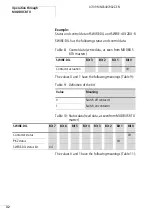
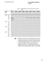
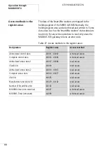
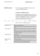
Control data areas
The control (output) data of the SmartWire stations are
located in two different register areas, one for the
abbreviated representation (two control bits per SmartWire
station, register area 40001 to 40002) and one for the full
representation (four control bits per SmartWire station,
register area 40003 to 40006). The MODBUS RTU gateway
does not support the simultaneous use of both of these data
areas, since this could cause inconsistencies between the
control data in the two register areas. To switch between the
two control data areas, you must switch the MODBUS RTU
gateway off and on again.
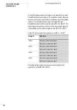
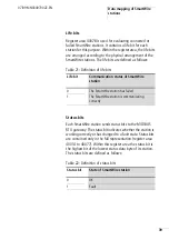
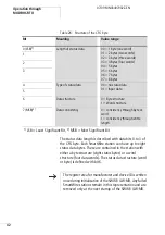
Check bits
The register area for parity bits is used to determine whether
a station on the SmartWire has failed or has an internal fault
state. Each SmartWire station has a parity bit. Within the
register area, the parity bits are arranged according to the
physical arrangement of the SmartWire stations. The parity
bits are defined as follows:
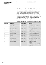
Table 20: Definition of parity bits
Parity bit
SmartWire station status
0
Station connected and working correctly
1
Station has failed or is defective
h
Each parity bit represents a logic OR link of the status and
life bit of its SmartWire station. It therefore contains the
key diagnostic information about its SmartWire station, so
that an additional evaluation of status and life bits may
not be necessary.
Summary of Contents for SWIRE-GW-MB
Page 14: ...10 07 09 MN03407002Z EN ...
Page 26: ...22 07 09 MN03407002Z EN ...
Page 30: ...26 07 09 MN03407002Z EN ...
Page 58: ...54 07 09 MN03407002Z EN ...
Page 63: ...Dimensions 59 07 09 MN03407002Z EN Dimensions M4 7 5 35 5 7 5 90 102 110 105 109 4 5 ...
Page 64: ...60 07 09 MN03407002Z EN ...