


Operation through
MODBUS RTU
28
07/09 MN03407002Z-EN
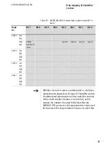
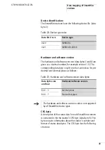
Data mapping of
SmartWire stations
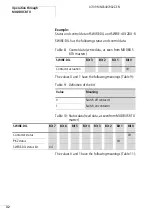
Within each MODBUS RTU device, the input and output level
data are stored in various registers (input register and
holding register).
For the MODBUS RTU gateway the status and control data
for the connected SmartWire stations are saved to the
holding register of the SWIRE-GW-MB, which contains the
following data:
• Status information (input data) of the SmartWire stations
• Control data (output data) of the SmartWire stations
• Parity bits of the SmartWire stations
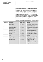
• Device and manufacturer’s ID of the SmartWire stations
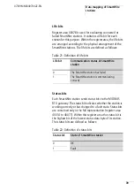
• Life bits of the SmartWire stations
• Number of connected SmartWire station
• Time value of the built-in MODBUS timer
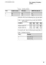
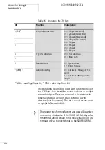
This data is saved to the registers as follows:
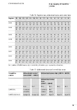
Table 6: Data mapping in the SWIRE-GW-MB
Designation
Register area
Data width:
Diagram
Abbreviated control
data
40001 - 40002
4 bytes
two bits per SmartWire stations
Complete control data
40003 - 40006
8 bytes
four bits per SmartWire station
Abbreviated
status data 1
40007 - 40008
4 bytes
two bits per SmartWire stations
Check bits
40009
2 bytes
1bit per SmartWire station
Abbreviated
status data 2
40010 - 40013
8 bytes
four bits per SmartWire station
Complete status data
40014 - 40077
128 bytes
eight bits per SmartWire station
Life bits
40078
2 bytes
1bit per SmartWire station
Station ID
40079 - 40142
128 bytes
eight bits per SmartWire station
Summary of Contents for SWIRE-GW-MB
Page 14: ...10 07 09 MN03407002Z EN ...
Page 26: ...22 07 09 MN03407002Z EN ...
Page 30: ...26 07 09 MN03407002Z EN ...
Page 58: ...54 07 09 MN03407002Z EN ...
Page 63: ...Dimensions 59 07 09 MN03407002Z EN Dimensions M4 7 5 35 5 7 5 90 102 110 105 109 4 5 ...
Page 64: ...60 07 09 MN03407002Z EN ...