


Operation through
MODBUS RTU
36
07/09 MN03407002Z-EN
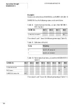
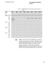
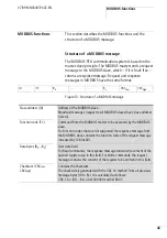
In the full representation all status and control bits of each
SmartWire station are output. The complete control data use
four bits of register area 40003 to 40006 for each SmartWire
station. The complete status data use eight bits per
SmartWire station within register area 40014 to 40077. The
table below shows the structure of the status data bytes of
a SmartWire station within register area 40014 to 40017.
Table 18: Status bytes for register area 40014 – 40017
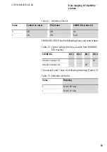
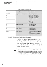
The table below shows the data contained within this
register for a SWIRE-4DI-2DO-R.
Register
High byte
40014
Low byte | status data byte 2
High byte | status data byte 1
40015
Low byte | status data byte 4
High byte | status data byte 3
40016
Low byte | status data byte 6
High byte | status data byte 5
40017
Low byte | status data byte 8
High byte | status data byte 7
Summary of Contents for SWIRE-GW-MB
Page 14: ...10 07 09 MN03407002Z EN ...
Page 26: ...22 07 09 MN03407002Z EN ...
Page 30: ...26 07 09 MN03407002Z EN ...
Page 58: ...54 07 09 MN03407002Z EN ...
Page 63: ...Dimensions 59 07 09 MN03407002Z EN Dimensions M4 7 5 35 5 7 5 90 102 110 105 109 4 5 ...
Page 64: ...60 07 09 MN03407002Z EN ...