


Connecting MODBUS RTU
17
07/09 MN03407002Z-EN
The following table lists the signals of SWIRE-GW-MB.
Table 3: Signals SWIRE GW-MB
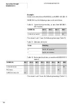
Data transfer with RS485
If you are using the RS485 communication standard, pins
5,6, 8 and 9 of the gateway’s D-sub socket are used for data
transfer. The Table 4 below lists the pin functions and
assignments of the 9.pin D-sub connector.
Pin
Signal name
Designation
1
Not used
–
2
RxD out
RS232 transmit
3
TxD in
RS232 receive
4
Not used
–
5
GND
Reference potential
6
+ 5V
+ 5V, electrically isolated
7
Not used
–
8
Rx/Tx – (A-Line)
RS485 receive/Send data N
9
Rx/Tx + (B-Line)
RS485 receive/Send data P
h
Caution!
For communication through RS485 use only pins 5,6,8 and
9! Using preassembled data cables that use pins 2 and 3
can damage the SWIRE-GW-MB or the other connected
device.
Summary of Contents for SWIRE-GW-MB
Page 14: ...10 07 09 MN03407002Z EN ...
Page 26: ...22 07 09 MN03407002Z EN ...
Page 30: ...26 07 09 MN03407002Z EN ...
Page 58: ...54 07 09 MN03407002Z EN ...
Page 63: ...Dimensions 59 07 09 MN03407002Z EN Dimensions M4 7 5 35 5 7 5 90 102 110 105 109 4 5 ...
Page 64: ...60 07 09 MN03407002Z EN ...