Communication
38
Eaton Remote Power Panel (RPP) User’s Guide 164202125—Rev 5
www.eaton.com/powerquality
X-Slot Cards
X-Slot cards allow the RPP to communicate in a variety of networking environments and with different types
of devices. The RPP has two available communication bays for any X-Slot, including:
l
Modbus
®
Card
– provides direct integration of the RPP's parameters (meters and status) to a Building
Management System (BMS) using the Modbus RTU protocol.
Note:
Either the Power Xpert Gateway Card or the Power Xpert Gateway PXGX PDP Card can be used.
l
Eaton Power Xpert
®
Gateway Card – Provides remote monitoring through a Web browser interface, e-mail,
and a network management system using SNMP; connects to a twisted-pair Ethernet (10/100BaseT)
network. Modbus Card TCP support provides direct integration of the RPP's parameters to a Building
Management System (BMS). It has a built-in switching hub that allows one additional network device to be
connected to the network without the requirement of an additional network drop.
l
Eaton Power Xpert
®
Gateway PXGX PDP Card – provides Web-enabled, real-time monitoring of Eaton power
distribution products (PDPs) through standard Web pages, Power Xpert Software, or third-party software.
An integral part of the Eaton Power Xpert Architecture, which provides end-to-end PowerChain
Management™ solutions, the PXGX PDP Card provides a central point to connect PDPs to the Ethernet
network. Modbus TCP support provides direct integration of the PDU's parameters to a Building
Management System (BMS). It has a built-in switching hub that allows one additional network device to be
connected to the network without the requirement of an additional network drop.
LAN and telephone drops for use with X-Slot cards must be provided by the customer.
See Figure 19 on page 35 for the location of the two X-Slot communication bays.
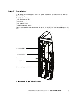
Figure 22. Optional X-Slot Cards
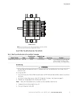
Control Terminals
Note:
For ease of control wiring installation on the Large RPP, loosen the screws securing the control pan
and slide the pan out (see Figure 23).
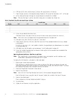
The cables should be connected to the control terminals with a mating connector. Input and output terminals
have a functional isolation from terminal to terminal. They are connected to the RPP chassis through individual
1 M
resistors.
Note:
If using a semiconductor switch type, pay attention to the proper polarity. A relay or other mechanical
control is preferred.
Power Xpert Gateway
PXGX PDP
EMP
Upstream
Downstream
100
100
Act
Act
Setup
Restart
Status
DHCP
Ident
Power
Modbus Card Card
Power Xpert Gateway Card
Power Xpert Gateway PXGX
PDP Card
Summary of Contents for Remote Power Panel
Page 1: ...Eaton Remote Power Panel RPP User s Guide ...
Page 2: ......
Page 3: ...Eaton Remote Power Panel RPP User s Guide ...
Page 63: ......
Page 64: ... 164202125 3 164202125 5 ...


