

Installing the UPS System
3-15
EATON
Powerware
®
9390 UPS (100–160 kVA) Installation and Operation Manual
S
164201554 Rev E
powerware.com
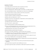
Installation Checklist
-
All packing materials and restraints have been removed from each cabinet.
-
Each cabinet in the UPS system is placed in its installed location.
-
The front shipping bracket is installed and adjusted, if the cabinet is not installed permanently.
-
A cabinet grounding/mounting kit is installed between any cabinets that are bolted together.
-
All conduits and cables are properly routed to the UPS and any ancillary cabinets.
-
All power cables are properly sized and terminated.
-
Neutral conductors are installed or bonded to ground as per requirements.
-
Battery cables are terminated on E4 (+) and E5 (-).
-
Battery UV trip and Aux contact signal wiring is connected from the UPS to the battery breaker.
-
LAN and telephone drops are installed.
-
All telephone and LAN connections have been completed.
-
A ground conductor is properly installed.
-
Air conditioning equipment is installed and operating correctly.
-
The area around the installed UPS system is clean and dust-free. (It is recommended that the UPS be
installed on a level floor suitable for computer or electronic equipment.)
-
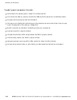
Adequate workspace exists around the UPS and other cabinets.
-
Adequate lighting is provided around all UPS equipment.
-
A 120 Vac service outlet is located within 7.5 meters (25 feet) of the UPS equipment.
-
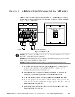
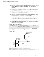
The REPO device is mounted in its installed location and its wiring is terminated inside the UPS cabinet.
The REPO switch must be a latching-type switch with a dedicated circuit.
-
The normally-closed (NC) Emergency Power-off contact (pins 1 and 2 on TB1) is jumpered if not used.
-
Alarm relays and building alarms are wired appropriately. (OPTIONAL)
-
A remote battery disconnect control is mounted in its installed location and its wiring is terminated inside
the UPS and battery cabinet. (OPTIONAL)
-
Accessories are mounted in installed locations and wiring is terminated inside the UPS cabinet.
(OPTIONAL)
-
The debris shield covering the UPS cabinet ventilation grill is removed.
-
Startup and operational checks are performed by an authorized Eaton Customer Service Engineer.
Summary of Contents for Powerware 9390-160/100
Page 1: ...Powerware 9390 UPS 100 160 kVA Installation and Operation Manual...
Page 225: ......
Page 226: ...164201554E 164201554 E...