

081505
C
164201554---8
DESCRIPTION:
DATE:
DRAWING NO:
SHEET:
REVISION:
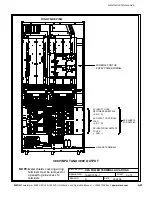
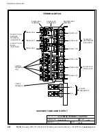
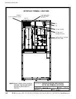
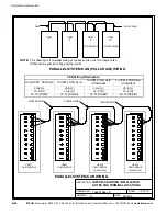
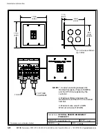
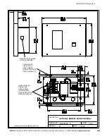
INTERFACE WIRING INSTALLATION
NOTES AND TERMINAL LOCATIONS
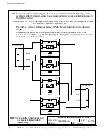
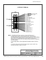
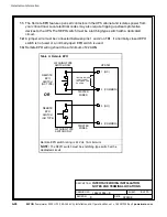
NOTE:
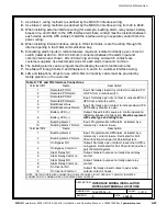
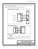
1. All building alarm inputs require an isolated normally-open or
normally-closed contact or switch (rated at 24 Vdc, 20 mA minimum)
connected between the alarm input and common terminal as shown. Building
alarm inputs can be programmed for use with either normally-open or
normally-closed contacts. All control wiring and relay and switch contacts are
customer-supplied.
2. The building alarms can be programmed to display the alarm functional
name.
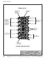
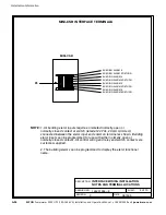
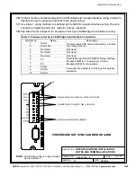
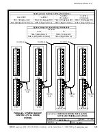
MINI-CSB INTERFACE TERMINALS
1
8
P5
BUILDING ALARM 3
BUILDING ALARM 3 RETURN
MINI-CSB
BUILDING ALARM 4
BUILDING ALARM 5
BUILDING ALARM 6
BUILDING ALARM 4 RETURN
BUILDING ALARM 5 RETURN
BUILDING ALARM 6 RETURN
4 of 13
Installation Information
A-36
EATON
Powerware
®
9390 UPS (100–160 kVA) Installation and Operation Manual
S
164201554 Rev E
powerware.com
Summary of Contents for Powerware 9390-160/100
Page 1: ...Powerware 9390 UPS 100 160 kVA Installation and Operation Manual...
Page 225: ......
Page 226: ...164201554E 164201554 E...