

POWER WIRING INSTALLATION NOTES
121504
C
164201554---5
DESCRIPTION:
DATE:
DRAWING NO:
SHEET:
REVISION:
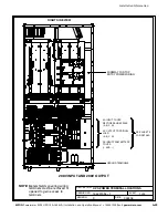
UPM 2
Battery
Bypass inputs to UPMs
UPM 1
Battery
UPM 3
Battery
UPM 4
Battery
Outputs from UPMs
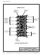
1A (30)
2A (35)
3A (40)
4A (45)
1B (25)
2B (20)
3B (15)
4B (10)
15 of 15
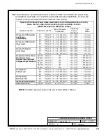
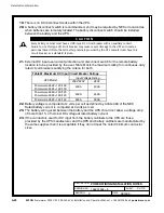
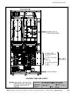
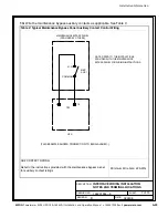
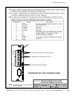
NOTE:
Wire lengths in the diagram and
formula are in feet and are for
example only.
Installation Information
A-26
EATON
Powerware
®
9390 UPS (100–160 kVA) Installation and Operation Manual
S
164201554 Rev E
powerware.com
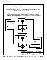
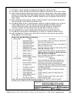
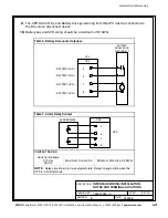
32.
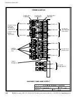
Required parallel system wiring length must be in accordance with the following formula,
as referenced to the diagram below, to ensure approximately equal current sharing when in
Static Bypass mode:
(Total length of 1A + 1B)
≅
(Total length of 2A + 2B)
≅
(Total length of 3A + 3B)
≅
(Total length of 4A + 4B)
(30 + 25)
≅
(35 + 20)
≅
(40 + 15)
≅
(45 + 10)
This rule has a tolerance of approximately
±
10% for the combined input and output wire
lengths.
If installing only two UPMs in a fully redundant system, this requirement is no longer
required, as each UPM is capable of supporting the full bypass requirement. However, this
would preclude future expansion.
Summary of Contents for Powerware 9390-160/100
Page 1: ...Powerware 9390 UPS 100 160 kVA Installation and Operation Manual...
Page 225: ......
Page 226: ...164201554E 164201554 E...