background image

Modbus Registers

Eaton Power Xpert Gateway PXGX PDP Card User’s Guide 164202122—Rev 1

59

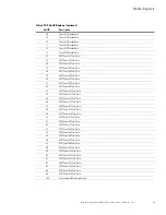
PDP Unit ID Numbers

Because the PDP consists of several panels of circuit breakers, set the Unit ID in the Modbus program to 
specify a specific PDP, a specific panel, or a specific breaker (see Table 6).

The PDP has a Unit ID of 0, 1, or 255. The same information can be obtained from any of these IDs. See “PDP 
Registers and Alarms” on page 61 for more info
rmation.

The panel Unit IDs range from 2 to 17. These summary data panel registers contain the total information for all 
the breakers in a specific panel. For example, the registers show the sum total current for each phase 
distributed by all the breakers. See “Panel Registers and Alarms” on page 62 for more information.

The breaker Unit IDs range from 18 to 33. These registers provide individual breaker data for the specified 
panel. See “Breaker Data and Alarms” on page 64 for more information on identifying specific breaker 
registers.

Note:

Selecting panel and breaker Unit IDs that are not available will return an error code. Currently available 
PDP model configurations are limited to eight panels, so only eight panel Unit IDs are used. Future 
models may be configured for up to 16 panels.

If there is an optional Environmental Monitoring Probe (EMP) installed, use Unit ID 254 to obtain EMP data. See 
“EMP (FC 04)” on page 66 for more information.

Table 6. PDP Unit ID Numbers 

Unit ID

Description

0, 1, and 255

PDP Summary Data

2

Panel #1 Summary Data

3

Panel #2 Summary Data

4

Panel #3 Summary Data

5

Panel #4 Summary Data

6

Panel #5 Summary Data

7

Panel #6 Summary Data

8

Panel #7 Summary Data

9

Panel #8 Summary Data

10

Panel #9 Summary Data

11

Panel #10 Summary Data

12

Panel #11 Summary Data

13

Panel #12 Summary Data

14

Panel #13 Summary Data

15

Panel #14 Summary Data

16

Panel #15 Summary Data

17

Panel #16 Summary Data

18

Panel #1 Breaker Data

19

Panel #2 Breaker Data

20

Panel #3 Breaker Data

21

Panel #4 Breaker Data

22

Panel #5 Breaker Data

23

Panel #6 Breaker Data

24

Panel #7 Breaker Data

25

Panel #8 Breaker Data

26

Panel #9 Breaker Data

27

Panel #10 Breaker Data

Summary of Contents for Power Xpert PXGX PDP

Page 1: ...Eaton Power Xpert Gateway PXGX PDP Card User s Guide ...

Page 2: ...ailable upon request for products with a CE mark For copies of the EC Declaration of Conformity contact Eaton Power Quality Oy Koskelontie 13 FIN 02920 Espoo Finland Phone 358 9 452 661 Fax 358 9 452 665 68 Eaton Power Xpert and X Slot are registered trademarks and PowerChain Management is a trademark of Eaton Corporation or its subsidiaries and affiliates Excel Internet Explorer Microsoft and Win...

Page 3: ...sks Essential to Initial Configuration 25 Changing the Passwords 26 Setting the Date and Time 26 Configuring SNMP Options 27 Community Strings and Trap Recipients 27 Changing SNMP Access 27 System Location and System Contact 28 Management from an SNMP NMS 29 Configuring Modbus TCP IP Options 29 Configuring HTTP and HTTPS 30 Configuring the Energy Management System EMS 30 Configuring E Mail Notific...

Page 4: ...ntity MIB Files 54 7 MODBUS REGISTERS Identifying the Breakers 56 PDU RPP Breakers 56 RPM Breakers 56 Pole Data 57 Obtaining the Modbus Register Map 57 Returning Error Codes 57 Modbus Register Addressing 58 Modbus Function Codes 58 Data Formats 58 Data Addressing 58 PDP Unit ID Numbers 59 PDP Registers and Alarms 61 PDP Registers FC 04 61 PDP Alarms FC 02 61 Panel Registers and Alarms 62 Panel Sum...

Page 5: ...ta and make informed network management decisions l Integrated communications with Eaton s Power Xpert Software monitor power devices in real time through Power Xpert Software l Simple Network Management Protocol SNMP support integrate and manage your PDP with third party network management software l Power quality data using Modbus Transmission Control Protocol TCP use this open communication pro...

Page 6: ... Protocol DHCP provide your local network administrator with the card s MAC address The MAC address is located on a label on the bottom of the card o MAC Address _______________________________ 4 If you are not going to use DHCP to provide any of the settings listed below contact your local network administrator for the settings Select DHCP or enter the values for manual configuration in the table...

Page 7: ...d are in the OFF position see Figure 1 Figure 1 Verify DIP Switches are OFF 2 Remove the X Slot cover from the PDP Retain the screws Note If there is another card already installed with an attached communication cable disconnect the cable and then remove the card 3 If not already done record the MAC address for future reference see Step 3 of the Installation Checklist 4 To prevent electrostatic di...

Page 8: ...e 164202122 Rev 1 4 5 Slide the card into the open slot and secure with the screws removed in Step 2 see Figure 2 and Figure 3 Figure 2 Install the PXGX PDP Card Power Xpert Gateway PXGX PDP EMP Upstream Downstream 100 100 Act Act Setup Restart Status DHCP Ident Power ...

Page 9: ...7 If you are connecting to another PXGX PDP Card or other Ethernet device connect an Ethernet cable not supplied to the Downstream Ethernet connector on the PXGX PDP Card Figure 3 Secure the Card and Install the Ethernet Cable Power Xpert Gateway PXGX PDP EMP Upstream Downstream 100 100 Act Act Setup Restart Status DHCP Ident Power Optional Second Ethernet Cable Connected to a Downstream Network D...

Page 10: ...m pxgx and download the powerxpert inf file Note the location of the file 2 Plug the supplied USB cable into the Setup port on the card see Figure 4 Figure 4 Install the USB Cable 3 Plug the other end of the USB cable into the USB port on the computer The Windows operating system detects new hardware Power Xpert Gateway PXGX PDP EMP Upstream Downstream 100 100 Act Act Setup Restart Status DHCP Ide...

Page 11: ...Windows XP go to Step 5 l For Windows 7 go to Step 6 5 The Found New Hardware Wizard Welcome window opens see Figure 5 Continue to Installing the USB Driver Software Windows XP on page 8 Figure 5 Found New Hardware Wizard Welcome Window 6 If a message displays indicating that the device driver software was not successfully installed click Ignore 7 Continue to Installing the USB Driver Software Win...

Page 12: ...dows XP 1 Select No not this time and click Next The Found New Hardware Wizard Install Software window opens see Figure 6 Figure 6 Found New Hardware Wizard Install Software Window 2 Select Install from a list or specific location Advanced and click Next The Found New Hardware Wizard Installation Options window opens see Figure 7 Figure 7 Found New Hardware Wizard Installation Options Window ...

Page 13: ...to install and click Next The Found New Hardware Wizard Hardware Type window opens see Figure 8 Figure 8 Found New Hardware Wizard Hardware Type Window 4 Select Network adapters and click Next The Found New Hardware Wizard Select Network Adapter window opens see Figure 9 Figure 9 Found New Hardware Wizard Select Network Adapter Window ...

Page 14: ...the powerxpert inf file downloaded in Connecting the Card to the Computer on page 6 Figure 10 Install From Disk Window 6 Click Browse The Locate File window opens 7 Go to the folder containing the powerxpert inf file that you downloaded in Step 1 of Connecting the Card to the Computer on page 7 8 Select powerxpert inf and click Open The folder containing the powerxpert inf file displays in the Cop...

Page 15: ...pter displays in The Found New Hardware Wizard Select Network Adapter window see Figure 12 Figure 12 Found New Hardware Wizard Select Network Adapter Window 10 Select Linux USB Ethernet RNDIS Gadget and click Next 11 If the caution message shown in Figure 13 displays click Continue Anyway Figure 13 Caution Message ...

Page 16: ...he Network Connections window to verify that the installation was successful see Figure 15 If Linux USB Ethernet RNDIS Gadget is listed in the Device Name column the USB driver has been successfully installed Figure 15 Network Connections Window 15 To verify the IP address assigned through DHCP continue to Verifying IP Addresses on page 17 16 To manually enter a fixed IP address for the card s net...

Page 17: ... the USB Driver Software Windows 7 To install the USB driver software on a computer running Windows 7 1 Open the Control Panel and select Hardware and Sound Devices and Printers see Figure 16 Figure 16 Control Panel Window Hardware and Sound 2 Select Device Manager to open the Device Manager window ...

Page 18: ...22 Rev 1 14 3 Expand Other devices and select RNDIS Ethernet Gadget see Figure 17 4 Right click and select Update Driver Software Figure 17 Device Manager Window 5 Select Browse my computer for driver software see Figure 18 Figure 18 Update Driver Software Window Search Method ...

Page 19: ... in Step 1 of Connecting the Card to the Computer on page 7 8 Click Open The folder displays in the Search for driver software in this location box see Figure 19 Figure 19 Update Driver Software Window Browse for Driver Software 9 Click Next 10 If the message Windows can t verify the publisher of this driver software displays select Install this driver software anyway see Figure 20 Figure 20 Windo...

Page 20: ...s see Figure 21 Figure 21 Update Driver Software Window Update Successful 12 To verify the device is installed a Go to Control Panel Hardware and Sound Devices and Printers Device Manager b Expand Network adapters c Verify that Linux USB Ethernet RNDIS Gadget is listed under Network adapters see Figure 22 Figure 22 Device Manager Window Verify Device Installation ...

Page 21: ...ucture changes In some cases DHCP may not be available or fixed IP addresses may be preferred for the PXGX PDP Card for example if some other networked device needs to reach the card at a fixed address To verify the IP addresses assigned through DHCP continue to Verifying IP Addresses To manually enter fixed IP addresses for the card s network connection continue to Assigning an IP Address on page...

Page 22: ...Getting Started Eaton Power Xpert Gateway PXGX PDP Card User s Guide 164202122 Rev 1 18 Figure 24 PXGX PDP Card Network Page ...

Page 23: ...ork page displays see Figure 24 on page 18 4 Clear the DHCP Enabled check box to enable manual configuration 5 Enter the IP Netmask and Gateway addresses in the Manual Configuration section and click Apply 6 Click OK to confirm 7 If you will be using a host name or host names for controlling access to the card type the server IP address in the Name Server field Up to three IP addresses can be ente...

Page 24: ...ress Manually assigned fixed IPv6 address Note Only the Gateway and Static addresses are user configurable The Link Local and Automatic addresses are automatically populated Note Dynamic Host Configuration Protocol for IPv6 DHCPv6 is not supported To manually enter a fixed IP address for the card 1 Open your Web browser and enter http 192 168 200 101 You are prompted to log on 2 Log on as administ...

Page 25: ...trator The user name and default password is admin The PXGX PDP Card s initial page displays see page 21 Figure 25 Initial Page Device Overview and Summary 3 Select Network from the Configuration menu to open the Network configuration page 4 You can enable or disable DHCP control by selecting or clearing the check box The default is DHCP enabled 5 If you want the card to access other network serve...

Page 26: ...he gateway address IP Address Netmask and Gateway fields 9 To test the card s network connection to other network servers such as an SMTP server you can ping request acknowledgement from the host Enter the IP address or hostname in the Ping test field and then click Test 10 Click Apply to save the settings or Discard to cancel the changes 11 Continue to Chapter 3 Configuring the Card on page 23 fo...

Page 27: ...uring the card close the browser or log off as admin To log off as admin select Log on as user from the Configuration menu Logging on as user sets the security level to read only This section explains l Navigating the card s Web page l Identifying monitored equipment l Configuring essential tasks l Changing the passwords l Setting the date and time l Configuring SNMP options and managing from an S...

Page 28: ... be configured to also display in the banner If there is an active alarm in the hardware a flashing alarm icon with an alarm message displays in the banner Click the alarm message in the banner to display the Open Alarms page The highest level of an alarm active in the PDP displays as follows l Red for critical l Yellow for caution l Blue for acknowledged but not closed still alarming Banner Menu ...

Page 29: ...erical limits l Overview The Overview displays a functional status diagram of the PDP The animated yellow line shows the direction of the energy flow To the right of the diagram a list of the most relevant current readings displays The List tab page displays a complete list of current readings l Summary Tab The Summary tab page displays essential data most often used to determine the overall statu...

Page 30: ...nated Universal Time UTC To set the date and time and temperature unit of measure 1 Select Date Time from the Configuration menu The default is to synchronize the date and time from the PC clock 2 To synchronize the card with Network Time Protocol servers select Synchronize with NTP server s and type the IP addresses or host names You can synchronize the card with up to three NTP servers The NTP s...

Page 31: ...d write 4 For SNMPv3 configuration enter a new read only username and password and read write username and password in the appropriate fields Passwords for SNMPv3 must be at least 8 characters long 5 To modify the Trap recipient community string field type a new name The default is public 6 Click Add to add a new trap recipient entry to the list The Recipient field populates with the next availabl...

Page 32: ...r is configured see Network Configuration on page 21 4 Click Apply and then OK to save the settings System Location and System Contact To set the system location and system contact 1 Select Network from the Configuration menu 2 Enter the physical location of the installed PDP in the System location field This value also displays on the card s Web page banner 3 Enter the information to identify som...

Page 33: ...using host names verify that the IP address of your network DNS Server is configured see Network Configuration on page 21 4 Click Apply and then OK to save the settings For information on Modbus registers see Chapter 7 Modbus Registers on page 55 See Returning Error Codes on page 57 to change how error codes are returned MIB Name Filename Description Eaton PDU MIB EATON PDU MIB txt Meters availabl...

Page 34: ...ames are saved on the PXGX PDP Card but they are not supported on the LCD panel of the hardware In the Ganging column select the type of breaker installed Select 0 of 0 if the breaker is not configured Select 1 of 1 for a single pole breaker 1 of 2 for a two pole breaker or 1 of 3 for a three pole breaker The fields automatically update for multi phase breakers Set the rating for each breaker set ...

Page 35: ...il settings 4 Click Test SMTP server connection to test the configuration for the SMTP server The SMTP Test Results window opens Close the window when you are done viewing Note If the SMTP test is successful the confirmation displays immediately A failed test response can take a longer to display Close the window if you want to terminate the test 5 Specify events to trigger an e mail to be sent to...

Page 36: ... the limit When the EMP temperature measure activates the alarm it can come out of the alarm state only by dropping below the Temperature Hysteresis value Enter a value between 0 and 10 percent The default is 2 percent 6 To set the humidity limits of the EMP enter 0 to 90 percent for the Humidity Upper Limit and the Humidity Lower Limit The default for the upper limit is 90 the default for the low...

Page 37: ...ile 3 To save the PXGX PDP Card settings and preferences a Click Save gateway configuration The card exports an XML file containing the PXGX PDP Card configuration settings b Click Save and enter a file name and location to save the XML file Restoring a Backup Note Restoring configuration settings overrides all changes made to the configuration settings since the backup file was created To restore...

Page 38: ...00 Act Act Setup Restart Status DHCP Ident Power EMP Port Stacked Indicators Upstream Ethernet Cable Port Downstream Ethernet Cable Port USB Port Restart Switch Table 2 Ethernet Port Indicators Indicator Label Illuminated Not Illuminated Upstream Ethernet Port 100 Indicates a valid 100 Mb Connection Link Indicates a valid 10 Mb Connection Link as long as the corresponding ACT indicator is illumina...

Page 39: ...the card boots the indicator remains off However if it remains off after two minutes there is a communication problem between the card and the PDP DHCP Amber The PXGX PDP Card is configured for DHCP and has obtained IP address information The use of DHCP has been disabled by the user or all ports configured for DHCP have failed to obtain IP address information IDENT Red A firmware update is in pro...

Page 40: ... caution critical or major l Time and date when the error occurred l The parameter that is in alarm l The alarm message that displays on the PDP control panel displays as a link l The condition of the alarm active is true inactive is false The condition of the alarm indicates the actual condition of the PDP 2 To view the specific alarm parameter data click the Alarm Message link The Summary page d...

Page 41: ...ew log 4 Select a name and location for the file if you chose to save the file when prompted Interval Log The interval log contains a set of samples of data values taken at regular intervals by the gateway To generate an interval log 1 Select Interval Log from the Logs menu 2 Select the name of the device 3 Select the interval 5 15 or 60 minutes 4 To limit the number of records type or select one ...

Page 42: ...ta Log Interval Log Event Log or System Log page 2 Click OK to erase the log otherwise click Cancel Upgrading the Card s Firmware The card s firmware may be updated by downloading the appropriate file from www eaton com powerxpert During the upgrade process the PXGX PDP Card does not monitor the PDP status To upgrade the firmware 1 Select Firmware from the Configuration menu 2 Select the Reboot wh...

Page 43: ...the transactions will not be as secure as with the root CA using HTTPS You can require secure transactions by configuring the card for HTTPS see Configuring HTTP and HTTPS on page 30 The performance of the card is not impacted by using secure transactions This section explains root CA installation for l Windows Internet Explorer 7 and Internet Explorer 8 l Mozilla Firefox l Google Chrome Installin...

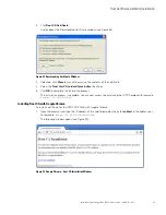
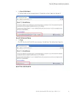
Page 44: ...PXGX PDP Card User s Guide 164202122 Rev 1 40 2 Click Root CA Certificate A File Download warning message displays see Figure 29 Figure 29 File Download Warning 3 Click Open The Certificate Window opens see Figure 30 Figure 30 Certificate Window for the PXGX PDP Card ...

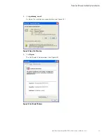
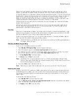
Page 45: ...r s Guide 164202122 Rev 1 41 4 Click Install Certificate The Certificate Import Wizard opens see Figure 31 Figure 31 Certificate Import Wizard 5 Click Next The Certificate Store window opens prompting you to specify a certificate store see Figure 32 Figure 32 Certificate Store Window ...

Page 46: ...Certificate Import Settings 8 Click Finish to complete the wizard A message displays informing you that Windows will automatically trust any certificate issued by this CA see Figure 34 Figure 34 Security Warning Message 9 Click Yes to install the CA A new message displays to verify that the import was successful 10 Click OK to close the message 11 Click OK to close the Certificate window 12 The in...

Page 47: ...nu b Click the Content tab c Click Certificates d Click the Trusted Root Certification Authorities tab and then locate and select the certificate name on the list see Figure 35 Note The name of the certificate starts with PowerXpert followed by the MAC address of the card Figure 35 Trusted Root Certification Authorities Tab e Click View to open the Certificate window see Figure 36 ...

Page 48: ...lick Close to close the Certificates window and click OK to close the Internet Options window Installing Root CA with Mozilla Firefox To install a certificate for the PXGX PDP Card with Mozilla Firefox 1 Open the browser and type the IP address of the card followed by the path ca html in the address bar For example http 10 222 49 63 ca html The following window opens see Figure 37 Figure 37 Mozill...

Page 49: ...s CA to identify web sites check box 5 Click OK to complete the installation process The installation process is complete You can now access the card using the HTTPS protocol for example https 10 222 49 63 Installing Root CA with Google Chrome To install a certificate for the PXGX PDP Card with Google Chrome 1 Open the browser and type the IP address of the card followed by the path ca html in the...

Page 50: ...202122 Rev 1 46 2 Click Root CA Certificate A File Download warning message displays at the bottom of the window see Figure 40 Figure 40 File Download Warning 3 Click Save The CRT Security Certificate file name displays at the bottom of the window see Figure 41 Figure 41 Security Certificate File ...

Page 51: ...er Xpert Gateway PXGX PDP Card User s Guide 164202122 Rev 1 47 4 Click gateway_ca crt An Open File warning message displays see Figure 42 Figure 42 Open File Warning 5 Click Open The Certificate Window opens see Figure 43 Figure 43 Certificate Window ...

Page 52: ...tall Certificate The Certificate Import Wizard Welcome window opens see Figure 44 Figure 44 Certificate Import Wizard Welcome Window 7 Click Next The Certificate Import Wizard Certificate Store window opens prompting you to specify a certificate store see Figure 45 Figure 45 Certificate Store Window Certificate Store Window ...

Page 53: ...ard window certificate displays a final verification see Figure 46 Figure 46 Certificate Import Wizard Completing the Certificate Import Wizard Window 10 Click Finish to complete the wizard 11 Click Yes to install the CA A new message displays to confirm that the import was successful 12 Click OK to close the message 13 Click OK to close the Certificate window The installation process is complete ...

Page 54: ...Scroll to the bottom of the window and click Manage Certificates c Click the Trusted Root Certification Authorities tab and locate and select the certificate name on the list see Figure 47 Note The name of the certificate starts with PowerXpert followed by the MAC address of the card Figure 47 Certificates Window Trusted Root Certification Authorities Tab d Click View to open the Certificate windo...

Page 55: ...XGX PDP Card User s Guide 164202122 Rev 1 51 Figure 48 View Certificate e When you are finished viewing the information click OK to close the Certificate window click Close to close the Certificates window and click Close again to close the Google Chrome Options window ...

Page 56: ... files l Eaton PDU MIB l Eaton EMP MIB l Eaton Power Meter MIB l Eaton PowerChain Device MIB l Eaton Alarms Traps MIB l Eaton OID Assignments l RFC 4133 Entity MIB l RFC 4268 Entity State MIB l RFC 4268 Entity State MIB Part 2 See the MIB files for detailed information about each MIB object Eaton PDU MIB The Eaton PDU MIB module contains objects and notifications for PDP Panel and Breaker informat...

Page 57: ... Power quality Power quality PQ index percentage of total harmonic distortion THD for current and volts Information Technology Industry Council ITIC performance curve l Real time measures Voltage currents and power measures l Minimum average and maximum Voltage currents frequency and power factor l Energy measures Watt VAR and VA hours l Power demand KW KVA and KVAR over the meter s demand period ...

Page 58: ...rovides standard objects for identifying and describing devices attached to the card The PXGX PDP Card is the first device entity the PDP is the second Panels and circuit breakers are assigned as individual device entities l The RFC 4268 Entity State MIB provides availability status measures for each device l The RFC 4268 Entity State MIB Part 2 provides possible state values for the Entity State ...

Page 59: ...ster Because there are many panels in a PDP it is necessary to identify a specific breaker and specify the panel containing that breaker It is likely that Breaker 5 in Panel 1 has different data than Breaker 5 in Panel 7 The tables in this chapter list sample names of the PDP parameters and their corresponding Modbus registers for l PDP summary data l Panel summary data l Breaker data The values o...

Page 60: ...r and is connected to all three phases positions 5 and 7 cannot be addressed as a single breaker Breaker 08 is configured as a two pole breaker and occupies two positions 8 and 10 so position 10 cannot be addressed The breaker map for your specific PDU RPP is available from the card s Web page see Obtaining the Modbus Register Map on page 57 When reading the breaker registers only the data associa...

Page 61: ...aining the Modbus Register Map and select the pole data when prompted from a device Note Either EMS Pole Data or RPM Pole Data register maps are available on the Web page depending on the product type but not both Obtaining the Modbus Register Map To view a list of the Modbus registers in your PDP 1 Select Modbus TCP Register Maps from the Documentation menu 2 Select the hardware type from the Sel...

Page 62: ...nslating each byte to decimal For example if today is May 17 2010 and the time is 10 45 and 20 seconds viewing each hex byte in decimal would yield the following data which is viewable as the year 10 month 05 day 17 hour 10 minutes 45 and seconds 20 See Time or Date FC 04 on page 67 for more information l BOOL A binary Boolean value of 0 or 1 BOOL is usually assigned to discrete input alarms Data ...

Page 63: ...ing specific breaker registers Note Selecting panel and breaker Unit IDs that are not available will return an error code Currently available PDP model configurations are limited to eight panels so only eight panel Unit IDs are used Future models may be configured for up to 16 panels If there is an optional Environmental Monitoring Probe EMP installed use Unit ID 254 to obtain EMP data See EMP FC ...

Page 64: ...anel 10 Pole Data 44 EMS Panel 11 Pole Data 45 EMS Panel 12 Pole Data 46 EMS Panel 13 Pole Data 47 EMS Panel 14 Pole Data 48 EMS Panel 15 Pole Data 49 EMS Panel 16 Pole Data 50 RPM Panel 1 Pole Data 51 RPM Panel 2 Pole Data 52 RPM Panel 3 Pole Data 53 RPM Panel 4 Pole Data 54 RPM Panel 5 Pole Data 55 RPM Panel 6 Pole Data 56 RPM Panel 7 Pole Data 57 RPM Panel 8 Pole Data 58 RPM Panel 9 Pole Data 5...

Page 65: ...e PDP alarms Your PDP may have different alarms PDP alarms are not registers but are discrete inputs and are read using FC 01 or FC 02 The PDP monitors the condition of several parameters and can activate an alarm status if a parameter is out of range For example if the input frequency is too high or too low the PDP can set the Input Frequency Fault Alarm To read the Input Frequency Fault Alarm se...

Page 66: ... the panel The registers contain the total information for all the breakers in the panel For example the AC Voltage between Phase A and Neutral is available in register 4010 To read the AC Voltage in Phase A at Panel 1 set the Modbus program to Unit ID 2 and register 4010 IP IP address of PDP Unit ID 2 Starting Register 4010 Number of Registers 2 Function Code 04 To read the AC Voltage in Phase A ...

Page 67: ... STRING 64 Display Name 1096 STRING 64 Serial Number 1276 STRING 64 Device Volts Rating 1355 UINT 4 Number of Phases 1361 UINT 2 Asset ID 1477 STRING 128 Breaker Rating 1607 UINT 2 Breaker Warning 1609 UINT 2 Breaker Overload 1610 UINT 2 Neutral Current Alarm 1612 UINT 2 Entity Admin State 3047 UINT 2 Entity Operating State 3048 UINT 2 Entity Readiness State 3049 UINT 2 Entity Alarm State 3050 UIN...

Page 68: ...P IP address of PDP Unit ID 23 Starting Register 1055 Number of registers 2 Function code 04 The Modbus program would return a value of the watts in Phase A for Breaker 1 in Panel 6 of the PDP at the specified IP address Table 10 Panel Sample Alarms FC 02 Name Coil Status Address Data Type Neutral Overload 1219 BOOL Panel Under Voltage 1238 BOOL Panel Over Voltage 1242 BOOL Panel Under Over Freque...

Page 69: ...e address similar to the data registers but these alarms are not data registers The alarms are discrete inputs and are read using FC 02 in the Modbus program AC MAX Current Phase B 1045 FLOAT 4 AC MAX Current Phase C 1047 FLOAT 4 Percent FL Current A 1049 FLOAT 4 Percent FL Current B 1051 FLOAT 4 Percent FL Current C 1053 FLOAT 4 Watts Phase A 1055 FLOAT 4 For example Breaker 2 starts at 1200 1000...

Page 70: ... Overload Warning alarm for Breaker 5 in Panel 8 of the PDP at the specified IP address EMP FC 04 Note See Configuring EMP Settings on page 32 for more information The optional EMP for the PDP can measure temperature and humidity Because the device can be located outside the PDP the reference is to auxiliary data In addition it contains two connections for monitoring the condition of auxiliary inp...

Page 71: ...byte in decimal would yield the following data which is viewable as the year 07 month 05 day 17 hour 10 minutes 45 and seconds 20 Viewing each hex byte as two byte unsigned integers would yield the following data Viewing each hex byte as binary would yield the following data Table 13 EMP Registers FC 04 Name Register Data Type Bytes Vendor Name 1032 STRING 64 Model Name 1064 STRING 64 Display Name...

Page 72: ... System Upgrade Kit EMS UGK or Power Distribution Rack PDR XCP communication protocol Network Protocols not limited to SNMP v1 or v3 over UDP IP Modbus TCP IP HTTP HTTPS BACnet WS NTP SMTP DHCP TCP IP including IPv4 and IPv6 Supported SNMP MIBs Eaton PDU MIB Eaton EMP MIB Eaton Power Meter MIB Eaton PowerChain MIB Eaton Alarms Traps MIB Eaton Object Identifier OID assignments RFC 4133 Entity MIB R...

Page 73: ...or after June 1 2004 and cannot be transferred This Warranty applies even in the event that the Product is initially sold by Company for resale to an End User LIMITED WARRANTY PERIOD The period covered by this Warranty for the Product installed and currently located in the fifty 50 United States the District of Columbia and Canada is twenty four 24 months from the date of purchase WHAT THIS LIMITE...

Page 74: ...OT WARRANT EQUIPMENT NOT MANUFACTURED BY COMPANY IF PERMITTED BY THE APPLICABLE MANUFACTURER COMPANY SHALL PASS THROUGH SUCH MANUFACTURER S WARRANTIES TO END USER COMPANY DOES NOT WARRANT SOFTWARE IF APPLICABLE TO THE PRODUCT INCLUDING SOFTWARE EMBEDDED IN PRODUCTS THAT IS NOT CREATED BY COMPANY WITHOUT LIMITING THE FOREGOING COMPANY SPECIFICALLY DOES NOT WARRANT SOFTWARE SUCH AS LINUX THAT WAS CR...

Page 75: ...OSTS NOT RELATED TO WARRANTY The End User shall be invoiced for and shall pay for all services not expressly provided for by the terms of this Warranty including without limitation site calls involving an inspection that determines no corrective maintenance is required Any costs for replacement equipment installation materials freight charges travel expenses or labor of Company representatives out...

Page 76: ... 164202122 164202122 1 ...

Reviews: