Modbus Registers
Eaton Power Xpert Gateway PXGX PDP Card User’s Guide 164202122—Rev 1
57
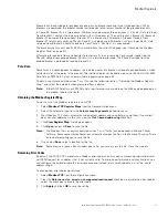
Breakers can be combined (or ganged) into one physical breaker covering two or three positions. When
breakers are combined, the breaker number corresponds to the lowest number of the grouped breakers.
In Figure 50, Breaker 01 is a three-phase, 20A breaker and occupies three positions (1, 2, and 3). Data returned
from Breaker 01 contains the data associated with all three phases. The next breaker is Breaker 04 (because
Breaker 01 occupies three positions). Breaker 07 is a two-phase, 20A breaker. A request for data from
Breaker 07 returns data covering Phases A and B. A single-phase, 60A breaker is shown in position 9. Data
returned from Breaker 09 contains only data from Phase C. Position 12 is unoccupied.
The breaker map for your specific RPM is available from the card's Web page (see “Obtaining the Modbus
Register Map” on page 57).
Attempting to read data from a nonexistent breaker results in an error code. For example, requesting the
Phase B voltage from ganged Breaker 05 results in a returned error code. The Phase B voltage from the
ganged breaker is obtained by reading Breaker 04.
Pole Data
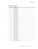
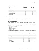
Sometimes it is advantageous to address the individual poles of a breaker instead of a ganged breaker, which
returns data for all the poles in the breaker. The individual poles can be addressed using the Unit IDs for EMS
Pole Data or RPM Pole Data as shown in Table 6 beginning on page 59.
To obtain a comma-separated values (*.csv) file, see the following section “Obtaining the Modbus Register
Map,” and select the pole data when prompted from a device.
Note:
Either EMS Pole Data or RPM Pole Data register maps are available on the Web page, depending on
the product type, but not both.
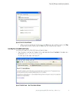
Obtaining the Modbus Register Map
To view a list of the Modbus registers in your PDP:
1.
Select
Modbus TCP Register Maps
from the Documentation menu.
2.
Select the hardware type from the
Select a map to generate
pull-down menu.
3.
Most Modbus-TCP clients automatically decrement addresses by one before using them. If your client
does not alter addresses in this way, clear the
Use 1-based addressing
check box.
4.
Click
View Register Map
. A dialog box opens.
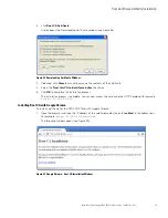
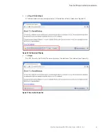
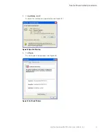
5.
Click
Open
to view or
Save
to save the file.
Note:
The Modbus file is a comma-separated values (*.csv) file that can be opened in Microsoft Excel
software. Some computer configurations automatically open the files in the Microsoft Excel software
instead of prompting you to save the file.
6.
If you select
Save
, select a location for the file.
Note:
Some browsers leave a blank window open after you save or view the file. Close the window.
Returning Error Codes
By default, the PXGX PDP Card returns a Modbus error code when it receives an incoming register/discrete/
coil READ request for an address that is not currently valid. To improve performance in some situations, you
can configure the card to disable this error response and instead return zero-filled data in all of the invalid
address ranges.
To change how error codes are returned:
1.
Select
Modbus TCP
from the configuration menu.
2.
Clear the
Return error (vs. zeros) on unsupported read request
check box to disable the error code or
select the check box to enable the error code.
3.
Click
Apply
and then
OK
to save the setting.


