Operation and Maintenance
Eaton Power Xpert Gateway PXGX PDP Card User’s Guide 164202122—Rev 1
35
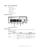
DIP Switch Description
DIP switch definitions for the PXGX PDP Card are listed in Table 4.
Open Alarms
Alarm notices display in three areas of the Web interface:
l
Banner:
If there is an active alarm(s) present on the PDP (Condition Active: true), a flashing alarm icon and
an alarm message display in the banner. The alarm icon and message reflect the actual condition of the
highest active alarm in the PDP. Clicking the alarm message displays the Open Alarms page.
l
Device Data Summary and List page:
If there is an open alarm(s), the “(Alarms Present)” message
displays at the top of the Device Data Summary and List page and the alarmed data value(s) is highlighted in
red text and continues to display in the alarm state until the alarm is closed.
l
Menu bar:
If there is an open alarm(s), “Open Alarms” and the number of active alarms display in red under
the Alarms menu. Clicking Open Alarms displays the Open Alarms page.
Table 3. Stacked Indicator Descriptions
Label
Color
Illuminated
Not Illuminated
STATUS
Green
Communication with the Power
Distribution Unit (PDU), Remote Monitor
Panel (RPP), Rack Power Module (RPM),
Energy Management System Upgrade Kit
(EMS-UGK), or Power Distribution Rack
(PDR) has been established.
Communication with the PDP has not been established.
As the card boots, the indicator remains off. However, if
it remains off after two minutes, there is a
communication problem between the card and the PDP.
DHCP
Amber
The PXGX PDP Card is configured for DHCP
and has obtained IP address information.
The use of DHCP has been disabled by the user, or all
ports configured for DHCP have failed to obtain IP
address information.
IDENT
Red
A firmware update is in progress. Do not
remove the card from the PDP.
A firmware update is not in progress.
POWER
Green
DC power is available to the card from the
PDP.
If all indicators are not illuminated, DC power is not
available from the PDP. This may indicate that the PDP is
off and unplugged.
Note:
During the power-on sequence, all four indicators illuminate briefly. Wait at least two minutes for the
card's boot process to complete before comparing the indicators to the table above because
indicators may turn on and off at different times in the boot process.
Table 4. DIP Switch Definitions
S1 Position Number
OFF Position (Default)
ON Position
1
Enable previously stored network configuration
settings (Normal mode)
Override the existing network settings and assign the local IP
address 169.254.1.1.
2
Reserved
Reserved.
3
Normal behavior
Reset the HTTP passwords to the defaults on boot (
user
and
admin
). After a successful boot, the switch should be turned
back off before rebooting the card.
4
Reserved
Reserved.
5
Reserved
Reserved.
6
Normal behavior
Reset the card to factory defaults on boot (after a successful
boot, the switch should be turned back off before rebooting the
card).


