


7
5. Installation
2
3
1
5
4
8
08
8
08
8
08
B022-U08
B022-U08
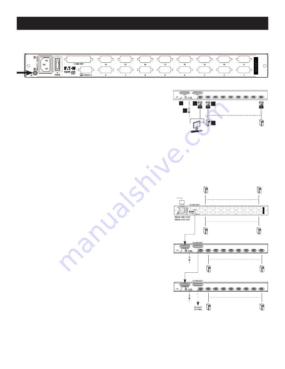
5.3 Grounding
To prevent damage to your installation it is important that all devices are properly grounded. Use the included grounding wire to ground the KVM
switch by connecting one end of the wire to the grounding terminal on the unit and the other end of the wire to a suitably grounded object.
5.4 Single-Station Installation
1. Ensure that power to all the connected devices has been turned off.
2. Connect the included USB/PS2 Combo Console Cable Kit to the console
connector on the back of the unit, then connect a monitor, mouse and
keyboard to the appropriate connectors on the cable kit. The distance between
the external console and the KVM switch must not exceed 66 ft. (20 m).
Note:
This step is optional for Console KVM Switches.
3. Use a P778-Series USB/PS2 Combo KVM Cable Kit to connect each CPU port to
a computer/server. The distance between the KVM switch and each connected
computer must not exceed 33 ft. (10 m).
4. Plug the power cord or power adapter cable into the KVM’s power jack, then plug into a UPS, surge protector or other AC power source.
Turn on the power switch for the console KVM.
5. Turn on the power to the computers.
5.5 Multiple Station (Daisy-Chained) Installation
To control even more computers, up to 31 B022-U08 KVM Switches can be daisy-chained down from the first station.
Note:
As many as 264 computers can be controlled from the unit’s integrated console in a complete installation.
To set up a daisy-chained installation:
1. Ensure that power to all the connected devices has been turned off.
2. Connect the included USB/PS2 Combo Console Cable Kit to the console
connector on the back of the unit, then connect a monitor, mouse and keyboard
to the appropriate connectors on the cable kit. The distance between the
external console and the KVM switch must not exceed 66 ft. (20 m).
3. Use a daisy-chain cable (described in the
Cables
section) to connect the
Chain
Out
port of the parent unit to the
Chain In
port of the child unit. The distance
between any two KVM switches in a daisy-chain must not exceed 49 ft. (15 m).
The distance between the first KVM switch and the last KVM switch in a daisy-
chain must not exceed 328 ft. (100 m), regardless of the number of KVM
switches in the entire chain.
4. Use a KVM cable kit (described in the
Cables
section) to connect the keyboard,
video and mouse ports of a computer to any available port on the KVM switch.
The distance between the KVM switch and each connected computer must not
exceed 33 ft. (10 m).
5. Repeat the above steps for any additional KVM switches and computers you
wish to add to the chain.
6. To power up the installation:
a. Plug in the power adapter for the first station. Wait a few seconds to allow the
unit to determine its Station ID.
b. Plug in the power adapters for each subsequent station in the installation (i.e.
second station, third station, etc.). Each KVM switch has an LED display on its
front panel to indicate its Station ID (the Station ID for the first station is
01
,
the ID for the second station is
02
, the ID for the third station is
03
, etc.).
In each case, wait for the Station ID to be displayed on the Station ID LED before
plugging in the next station.


