Technical Data
Effective: May 1998
Page
1
TD.44A.01.T.E
Cutler-Hammer
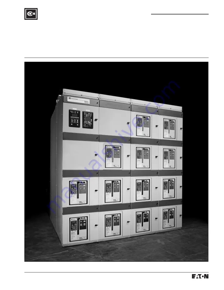
Magnum DSMetal-EnclosedLow-VoltageSwitchgear
New InformationMailed to: E, C/32-000B
www
. ElectricalPartManuals
. com
Page 1: ...nical Data Effective May 1998 Page 1 TD 44A 01 T E Cutler Hammer Magnum DS Metal Enclosed Low Voltage Switchgear New Information Mailed to E C 32 000B w w w E l e c t r i c a l P a r t M a n u a l s c...
Page 2: ...and 200 kA short circuit bus bracing without preced ing current limiting fuses Optional metal barriers isolates the cable compartment from the bus compartment Many other features for coordinated safe...
Page 3: ...as been tested for short circuit values of 85 000 amperes for a full 60 cycles Table R3 Standards Magnum DS switchgear conforms to the following standards NEMA SG3 and SG5 CSA ANSI C37 20 1 C37 51 and...
Page 4: ...otection In addition short delay protection may be set to the maximum instantaneous level effectively disabling short delay pro tection if instantaneous protection is turned off Under no condition is...
Page 5: ...400 400 1 25 1 50 1 75 2 00 2 50 3 00 3 75 5 00 600 600 1 25 1 50 1 75 2 00 2 50 3 00 3 75 5 00 800 800 1 25 1 50 1 75 2 00 2 50 3 00 3 75 5 00 1000 1000 1 25 1 50 1 75 2 00 2 50 3 00 3 75 5 00 1200...
Page 6: ...int indicated by rapid flashing of unit status LED on the product nominal occurs at 110 of the lr current with a 5 tolerance The short delay settings have conventional 100 5 as the pickup points 5 Wit...
Page 7: ...ing Plug ln 5 The instantaneous settings have conventional 100 10 as the pickup points 6 For additional curve tolerances contact Cutler Hammer 7 Total clearing times shown include the response times o...
Page 8: ...he rating plug is for 50 Hz and 60 Hz applications 8 Curves apply from 20 C to 50 C ambient temperatures above 95 C cause automatic trip 9 With zone interlocking on ground fault utilized and no restra...
Page 9: ...3 0 3 0 3 0 3 0 3 0 3 0 3 0 3 0 3 0 3 0 3 0 6 0 3 0 3 0 3 0 3 0 3 0 3 0 3 0 6 0 6 0 3 0 3 0 3 0 3 0 3 0 3 1 2 0 6 0 6 0 3 0 3 0 3 0 3 0 3 4000 4000 5 4000 1 0 3 0 3 0 3 0 3 0 3 5000 5000 5 5000 1 Refe...
Page 10: ...a clean dry room with filtered and or pressurized clean air This method permits the use of standard indoor switchgear and avoids the derating effect of non ventilated enclosures 3 Salt spray excessiv...
Page 11: ...mmable types of transformers eliminates necessity of vaults Efficient space utilization Advantages of Magnum DS Unit Substations Complete coordination both mechanical and electrical Extreme flexibilit...
Page 12: ...ar to those on radial unit substations If required and equipped with the appropriate relaying either trans former can be removed from service and isolated with no interruption of service on either bus...
Page 13: ...ith down stream devices Maximum capabilities of transformers of various types in terms of kVA and secondary current are given in Tables A1 through A4 It will be noted that the maximum ratings will oft...
Page 14: ...otors Contactors are recom mended for this application when there are a number of daily operations involved When system short circuits are less than 40 times the motor full load current the motor brea...
Page 15: ...ounded but in some very rare cases it is grounded at one corner of the delta or at some other point When the source is wye connected it can be grounded or ungrounded and when grounded the grounding is...
Page 16: ...solid state trip unit is in addition to the usual phase protection The ground element has adjustable pickup with calibrated marks as shown in Tables R8 and R9 and adjustable time delay The input curr...
Page 17: ...r equipment main tenance and hence reduce the occur rence of unplanned shutdowns Indication and Alarm Circuits When a fault is detected an adjustable time delay is provided to override tran sients Whe...
Page 18: ...hite pulse light off System control switch in normal position Reset control switch in either auto or manual Test Turn and hold the system control switch in the test position Phase B will be grounded v...
Page 19: ...formers HV 600 Max Delta To Distribution Equipment C B A 3 2 1 AM 51N Pulser Resistor Grounding Resistor G High Resistance Grounding Assembly Test Resistor Control Circuit CLF CLF CLF G R W Artificial...
Page 20: ...nded 20 20 Standard resid ual ground pro tection for single source systems and source ground per SK 5 for multiple ground sources Mini mum pickup 0 50 sec time delay Ground 3 wire or 4 wire as require...
Page 21: ...type of application Cutler Ham mer should be consulted for the actual bill of materials to be used The appli cation becomes rather complex if sin gle phase to neutral loads are being served X X N1 C B...
Page 22: ...Trip Unit GF Trip Unit GF Trip Unit 0 22 Sec 0 22 Sec 0 50 Sec 0 35 Sec GF Trip Unit TIE 52 1 52 T Bus 1 52 2 Bus 2 Bus 2 Neutral Connection Bus 1 Neutral Connection 52 T 33T 52 T Typical Feeder Thes...
Page 23: ...DS 608 MDS 408 MDS 408 MDS 408 MDS 408 MDS 408 MDS 408 1000 5 75 2778 50000 100000 150000 250000 500000 Unlimited 35900 41200 43300 45200 46700 48300 5600 41500 46800 48900 50800 52300 53900 MDS 632 M...
Page 24: ...DS 408 MDS 408 MDS 408 MDS 408 MDS 408 MDS 408 MDS 408 MDS 408 MDS 408 MDS 408 1500 5 75 1804 50000 100000 150000 250000 500000 Unlimited 20600 24900 26700 28400 29800 31400 7200 27800 32100 33900 356...
Page 25: ...08 MDS 408 MDS 408 MDS 408 MDS 408 MDS 408 MDS 408 MDS 408 MDS 408 MDS 408 1500 5 75 1443 50000 100000 150000 250000 500000 Unlimited 16500 20000 21400 22700 23900 25100 5800 22300 25800 27200 28500 2...
Page 26: ...eder 800 1600 2000 3200 Main 4000 5000 Main 4000 5000 Feeder 800 1600 2000 3200 Feeder 800 1600 2000 3200 Blank or Instrument 44 1118 Fig 6 44 1118 Fig 7 Maximum indoor shipping section width is 5 ver...
Page 27: ...Feeder 4000 5000 44 1118 Fig 11 44 1118 Fig 12 Maximum indoor shipping section width is 5 vertical sections or 120 inches 3048 mm whichever is smaller Maximum outdoor shipping width is 96 inches 2438...
Page 28: ...5000 Tie 4000 5000 Tie 4000 5000 Main 4000 5000 Feeder 800 1600 2000 3200 Feeder 800 1600 2000 3200 Blank or Instrument 44 1118 Fig 18 44 1118 Fig 19 Maximum indoor shipping section width is 5 vertic...
Page 29: ...ansformer connections etc All vertical sections are 92 inches 2339 mm high plus 4 inches 102 mm for ventilators and non removable lifting angle When a top of gear breaker lifter is used height is 99 i...
Page 30: ...izontal Cross Bus Area Vertical Bus Riser Area Lifting Plate Metal Enclosed Shipping Split Terminal Blocks Optional top of gear Breaker Lifter Magnum DS Metal Enclosed Low Voltage Switchgear Applicati...
Page 31: ...eft to right center of lineup From the front 26 inches 660 mm FC is the recommended front clearance for breaker removal with top of switchgear mounted breaker lifter If a portable breaker lifter is to...
Page 32: ...in 1829 mm 78 in 1981 mm 84 in 2134 mm 90 in 2286 mm 950 432 1000 455 1050 477 1100 500 1150 523 1200 545 11 in 279 mm Transition 60 in 1524 mm 66 in 1676 mm 72 in 1829 mm 78 in 1981 mm 84 in 2134 mm...
Page 33: ...ce interlocks are supplied on breakers and in compartments where the compartments are of the same physical size to assure an incorrect breaker cannot be inserted Key Interlock Switchgear Mounted Break...
Page 34: ...00 of main bus rating as standard Half 50 neu trals and neutral ratings up to a maxi mum of 6000 amperes are available as an option Ground A ground bus is furnished the full length of the switchgear a...
Page 35: ...cuit breaker The termi nal blocks are rated 30 amperes and will accept bare wire ring or spade ter minals for wire size ranges of 22 to 10 Extruded loops are punched in side sheets of the vertical wir...
Page 36: ...ndary Terminal Compartment Door Devices such as control push buttons breaker control switches indi cating lights and test switches can be mounted on these panels within space limitations The ammeters...
Page 37: ...he breaker closing springs are charged either through the manual charging handle or by the optional charging motor The breaker is mechanically interlocked to prevent closing of the breaker until the c...
Page 38: ...n the breaker Optional Breaker Attachments and Accessories a Shunt trip on manually operated breakers for any standard control voltage b Auxiliary contacts on manually or electrically operated breaker...
Page 39: ...CNC C5 CNO C11 CNO B30 B29 M M C7 C8 C10 C9 CNC CNO CNC B15 B14 C1 C2 C4 C3 C12 CNO C6 Breaker Auxiliary Contacts Shown with Breaker in Open Position Breaker Auxiliary Contacts Shown with Breaker in...
Page 40: ...tilize Belleville type spring washers to main tain maximum joint integrity through continuous thermal cycling The bus system shall be suitable for applica tions on power systems requiring a 100 150 20...
Page 41: ...y means of a portable plug in test device Both electrically operated and manu ally operated breakers shall have stored energy operating mechanisms The device to close the breaker shall be by means of...
Page 42: ...Technical Data Effective May 1998 Page 42 TD 44A 01 T E Cutler Hammer w w w E l e c t r i c a l P a r t M a n u a l s c o m...
Page 43: ...Technical Data Effective May 1998 Page 43 TD 44A 01 T E Cutler Hammer w w w E l e c t r i c a l P a r t M a n u a l s c o m...
Page 44: ...echnical Data Effective May 1998 Page 44 TD 44A 01 T E Printed in U S A Cutler Hammer Cutler Hammer Magnum DS Metal Enclosed Low Voltage Switchgear w w w E l e c t r i c a l P a r t M a n u a l s c o...