40
User Manual
MN032006EN
Effective December 2017
415U Condor-long-range
wireless I/O and gateway
EATON
www.eaton.com
Adding mapping parameters
Before adding or modifying a module’s TCP or RTU mappings, make
sure that the Modbus Master TCP Client and RTU Master checkbox
is selected at the top of the Modbus configuration screen (see
Figure 61
). Click the Modbus TCP Client or the RTU Master subtab,
depending on the connected device. Then, click
Add
to add a new
mapping,
Edit
to edit a selected mapping, or
Delete
to delete a
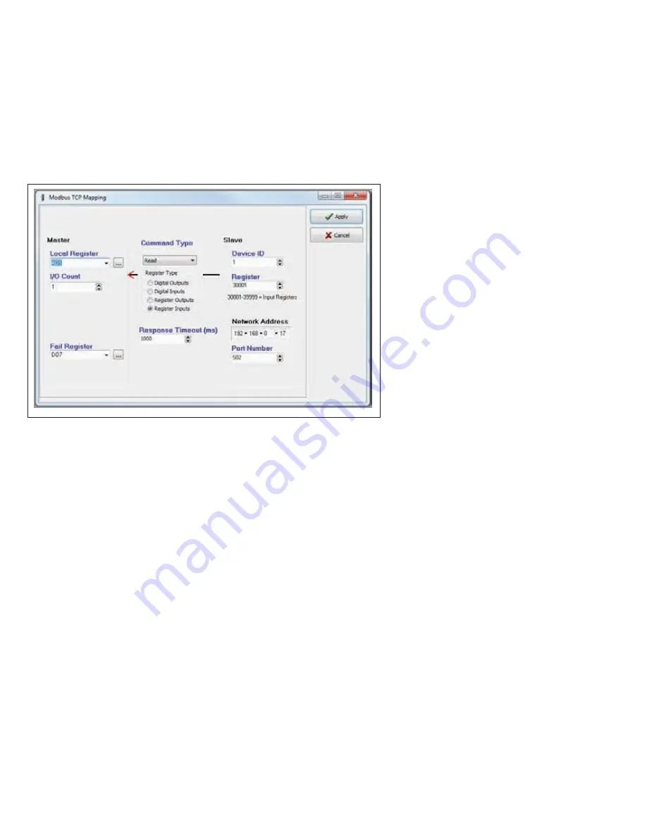
selected mapping. Clicking Add or Edit displays the screen in
Figure 62
, where you can specify mapping parameters.
Both Modbus TCP client and RTU master mappings have similar
parameters, the only difference will be the slave communication
path. For example, Modbus TCP client mappings will use a network
address and port while RTU master mappings will use a serial port.
Figure 62. Modbus TCP client mapping
Local Register (Master)
When the Function Code Modbus command is “Read” the Local Register field will be the destination
register(output location) on the local device. When the Function Code command is“Write” the Local
Register field will be the originating register (input location) on the local device.
I/O Count
The number of consecutive I/O values in the mapping.
Function Code (Command Type)
The Function Code Modbus command determines if the command will be “Read” or “Write” and what
type of register will be used. When entering a mapping, you need to select “Read” or “Write” from the
drop-down list in the Command Type field, and then select one of the four radio buttons representing the
register types. Selecting the register type will change the Destination (slave) register address range to a
suitable range.
Destination Register (Slave)
The register location on the TCP server/RTU slave device. The register selection offered will be appropriate
for the Modbus command selected in the Command field.
Device ID
The unit address (device ID) of the Modbus TCP server or Modbus RTU slave.
Server IP Address
Network Address
(TCP client only.) The IP address of the Modbus TCP server.
Server Port (TCP Client only)
The server port of the slave device, Modbus TCP will usually be the standard port address of 502.
Serial Port (Modbus RTU only)
This is the serial port used to connect to the device. Select the port from the drop-down list.
Response Time
The amount of time the TCP client or Modbus master waits for a response from a TCP server or an RTU
slave device before registering a Communications Fail.
Fail Reg
The Comms Fail indication register can be a physical output, such as DIO #1–8 (Reg 1-8), which will turn
on a digital output when in fail. It can also be configured as an internal holding register (Reg 30501),
which will show the fail indication as well as any Modbus error codes. This is useful for diagnosing
communication problems. For Modbus error code descriptions, see “Modbus error codes” on
page 78
.


